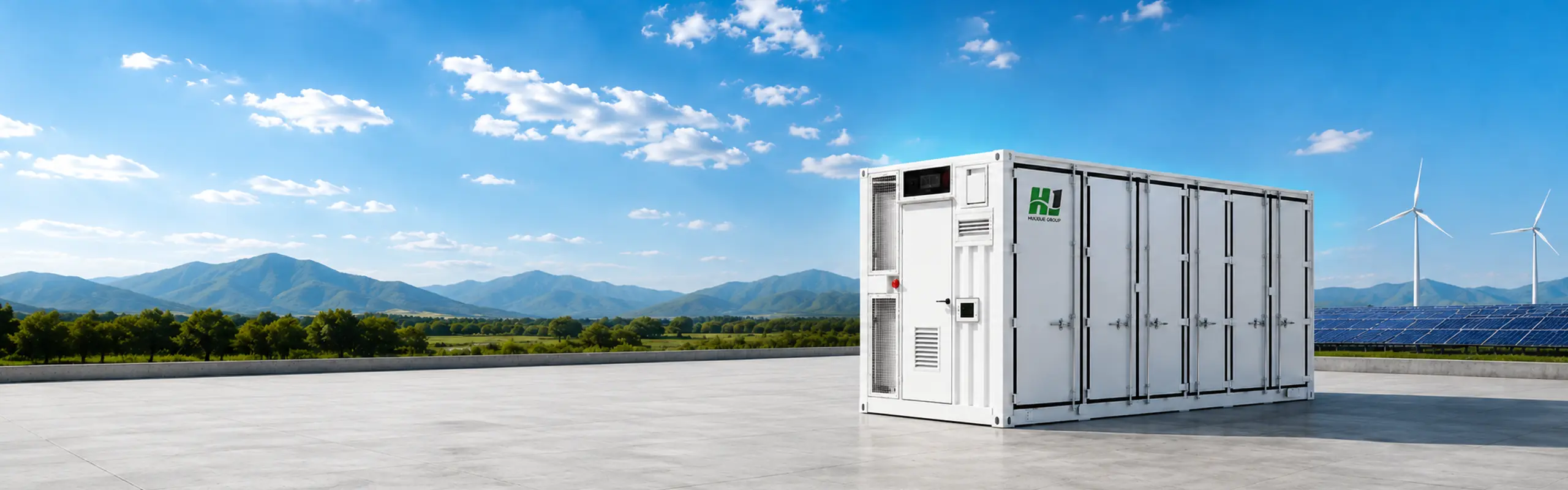
Energy Storage Containers
Delivering two cooling platforms within one project‑tailored system, our energy storage containers let you evaluate air‑cooled and liquid‑cooled platforms against energy duty, site conditions and integration scope.
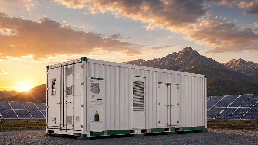
Straightforward thermal management. Flexible project scope.
2.0–5.0 MWh · primarily 40 ft
A configurable platform for projects that prioritize accessible maintenance and conventional industrial cooling.
View configuration labels
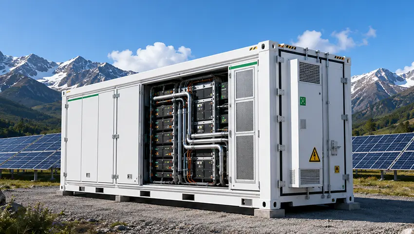
Higher energy density. More controlled cell temperatures.
2.5–6.25 MWh · 20 ft
A compact platform for projects where energy density, temperature uniformity and frequent cycling shape the design.
View configuration labels
Choose the thermal strategy before the model number
The right platform depends on duty, space, environment and maintenance—not capacity alone.
Air-cooled
- •Proven, straightforward thermal design
- •Flexible for diverse site conditions
- •Simpler maintenance and integration path
Liquid-cooled
- •Higher energy density in a compact footprint
- •More controlled cell temperatures
- •Better fit for frequent cycling priorities
| Decision factor | Air-cooled | Liquid-cooled |
|---|---|---|
| Published range reviewed | 2.0–5.0 MWh | 2.5–6.25 MWh |
| Typical container format | Primarily 40 ft | 20 ft |
| Thermal approach | Industrial air conditioning / forced air | Liquid cooling |
| Energy-density direction | Conventional | Higher-density platform |
| Best starting point when | Maintenance simplicity and conventional cooling lead | Footprint, temperature uniformity or frequent cycling lead |
| Final confirmation | Project-specific | Project-specific |
Published ranges summarize the reviewed HighJoule pages. Final availability, model identity and system boundary must be confirmed against the current approved datasheet.
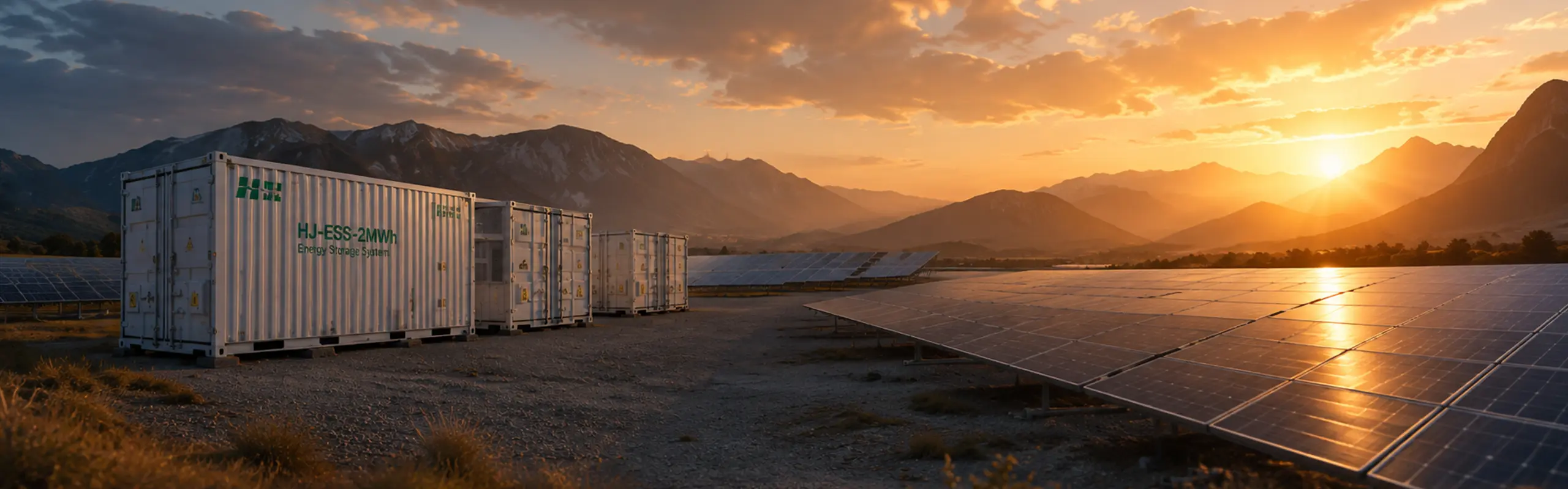
Ready to narrow the platform?
Compare duty, footprint and site conditions — then share your project requirements to identify the best-fit cooling platform.
Submit Project RequirementsConfirm the system boundary before comparing price
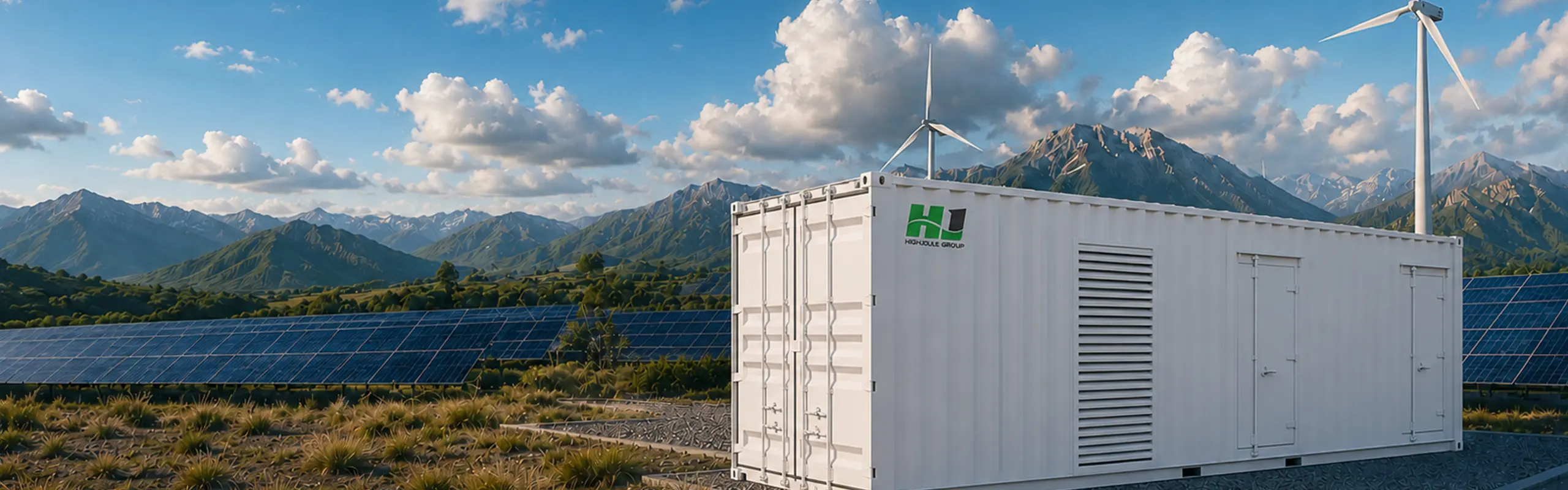
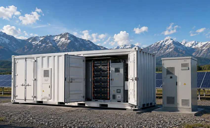 Conceptual visualization
Container scope
- ✓Battery system
- ✓BMS
- ✓Thermal management
- ✓Fire detection & suppression
- ✓Container auxiliaries
Confirm per configuration / project
- ○PCS
- ○Transformer
- ○Switchgear
- ○EMS / site controller
- ○Grid interface
- ○Installation & commissioning
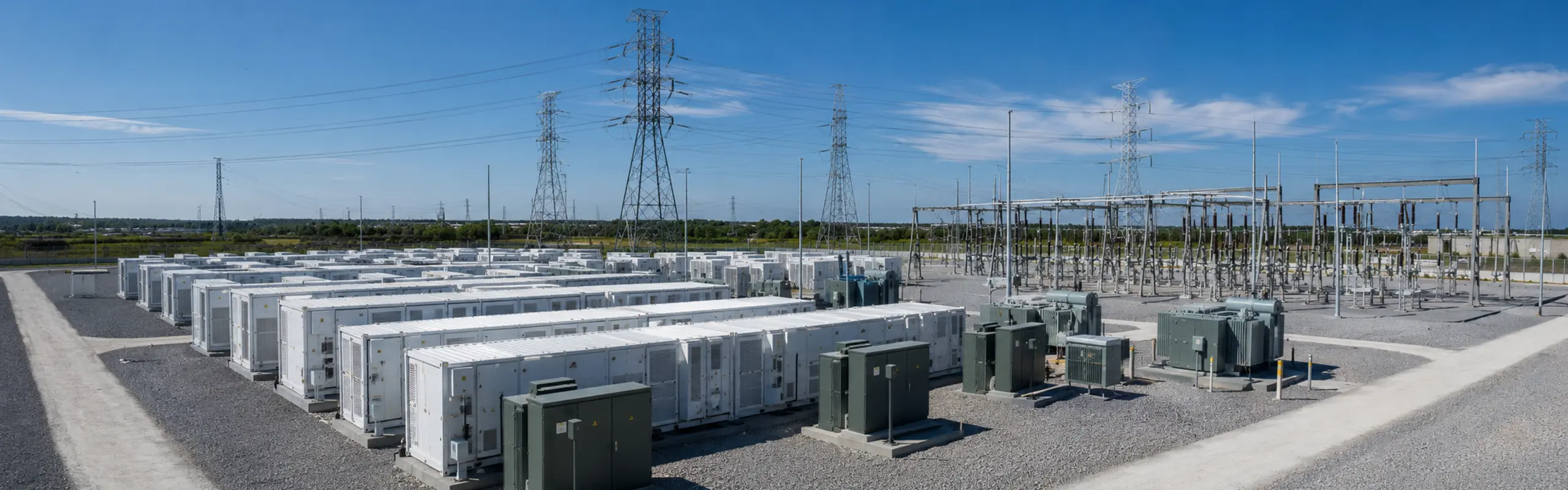
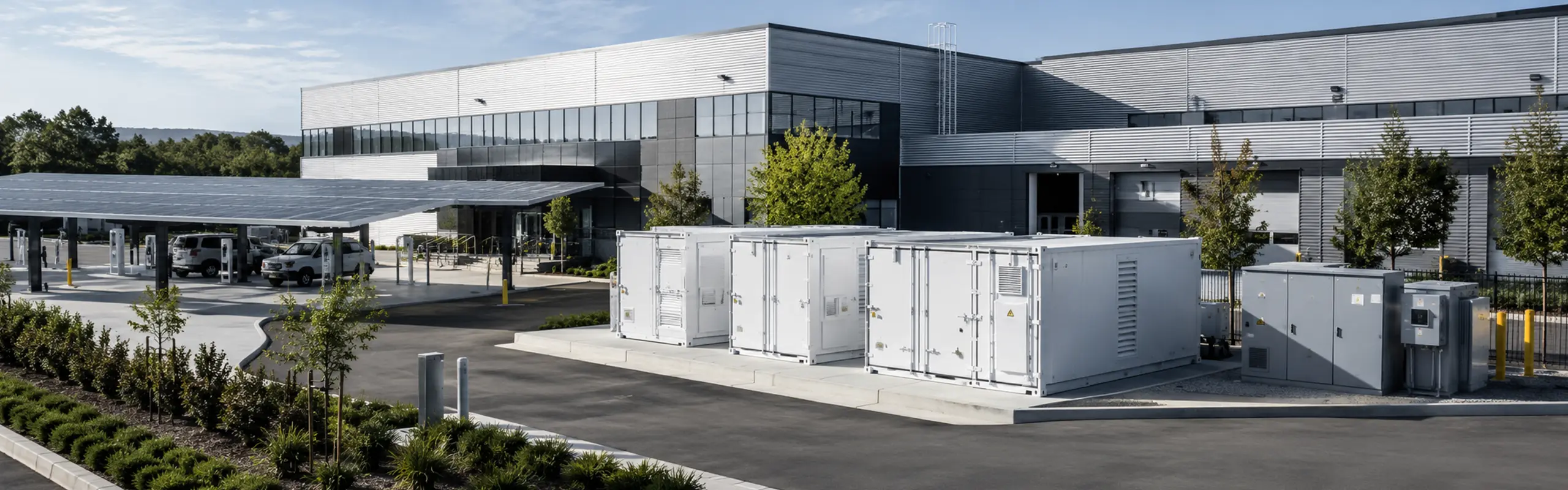
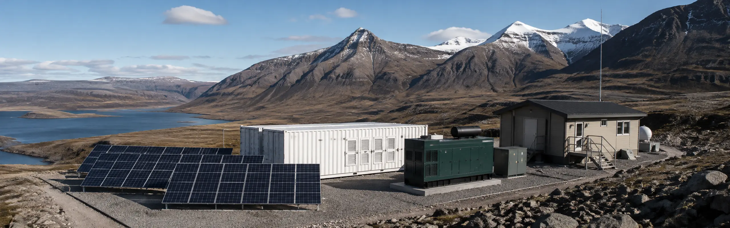
Built for project-specific energy storage integration
Utility and grid projects
Power and duration are coordinated with the grid interface and project-side equipment.
Industrial and commercial
The platform is configured around load profile, tariff strategy, footprint and operating conditions.
Microgrid and remote energy
Controls, generation sources and backup requirements define the integration scope.
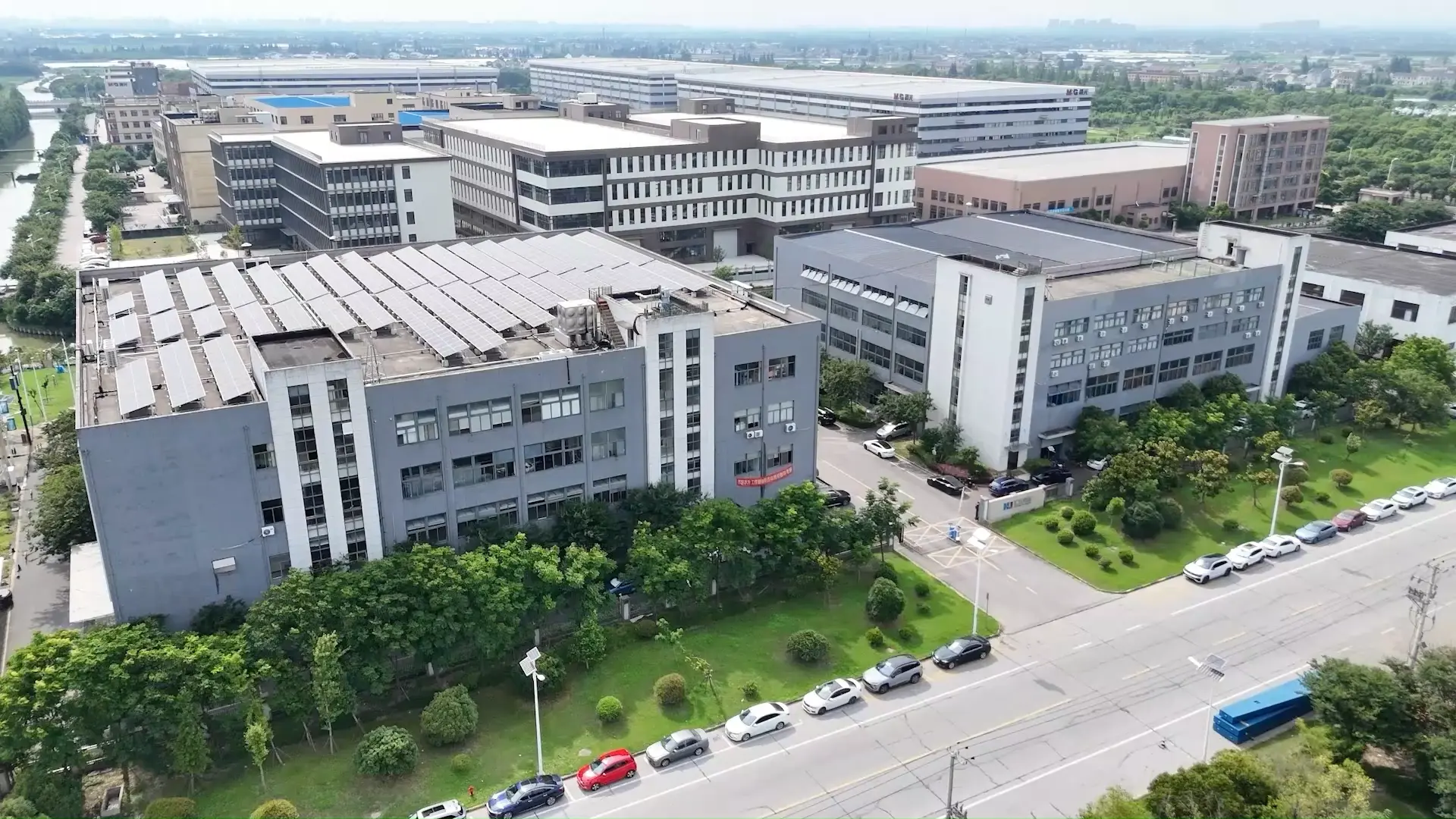
Manufacturing Capability
From system integration and assembly to rigorous testing and delivery, our energy storage systems are built for real project requirements.
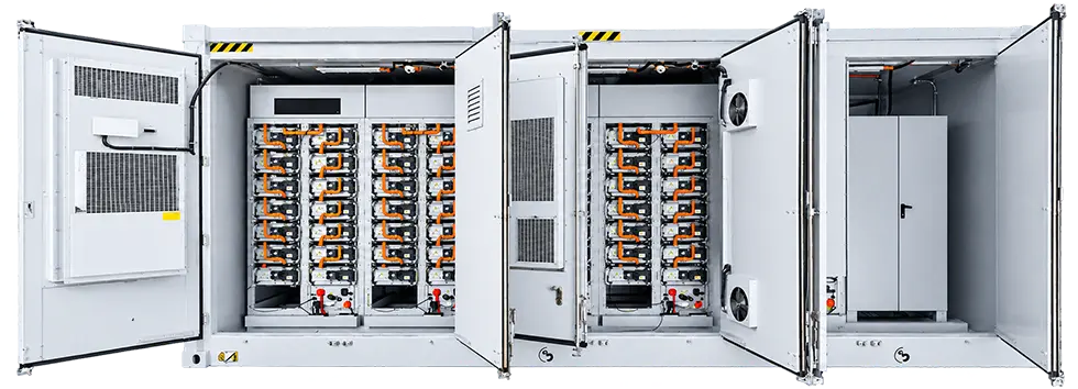
System Integration
Professional integration of battery, PCS, EMS and other core components.
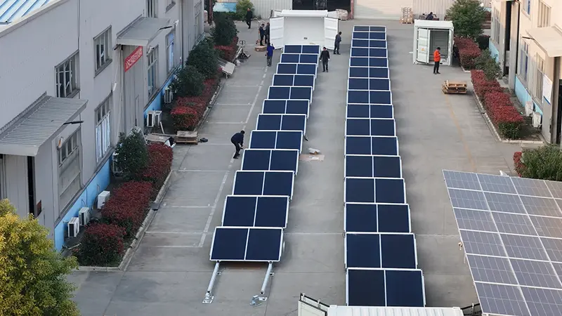
Assembly Process
Standardized assembly process ensures reliability and consistency.
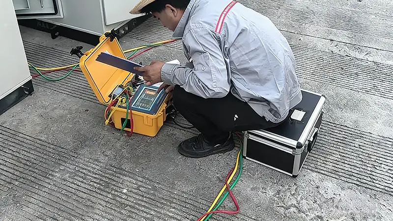
Quality Inspection
Multiple inspections at every stage to guarantee product quality.
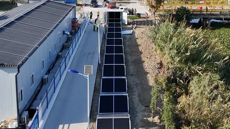
System Testing
Comprehensive functional, electrical and safety testing before delivery.
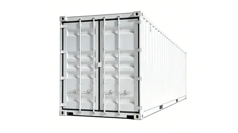
Finished Products
All systems are fully tested and ready for deployment.
Delivery & Shipping
Secure packaging and efficient logistics to project sites.
FAQ
Frequently asked questions
A: Air-cooled systems use conditioned or forced air to manage battery temperature. Liquid-cooled systems circulate coolant through a dedicated thermal circuit, supporting more uniform temperature control and higher packaging density. Final suitability depends on duty cycle, climate, footprint and maintenance requirements.
A: Frequent cycling increases thermal-management importance. Liquid cooling may offer advantages where temperature uniformity and higher utilization are priorities, but the final choice must be checked against the cell, duty profile and operating environment.
A: No. Container length alone does not determine energy capacity. Cell format, rack arrangement, cooling architecture, service clearances and system boundary all affect usable capacity.
A: PCS and EMS appear in some reviewed integrated configurations, while transformer, switchgear and site controller scope varies. The proposal and scope sheet must explicitly state what is included and what remains project-side.
A: Start from required power, usable energy and discharge duration. Grid service, peak shaving, backup and renewable integration can produce different power-to-energy ratios even at the same MWh capacity.
A: They must not be assumed identical. Certifications and standards are tied to the exact model, component set, market and current revision. Request the evidence package for the selected configuration.
A: Provide the load profile, required power and duration, grid interface, ambient and site conditions, footprint and access limits, required equipment scope, delivery destination and compliance requirements.
Have More Questions?
Fill out the form below and our team will get back to you within 24 hours.
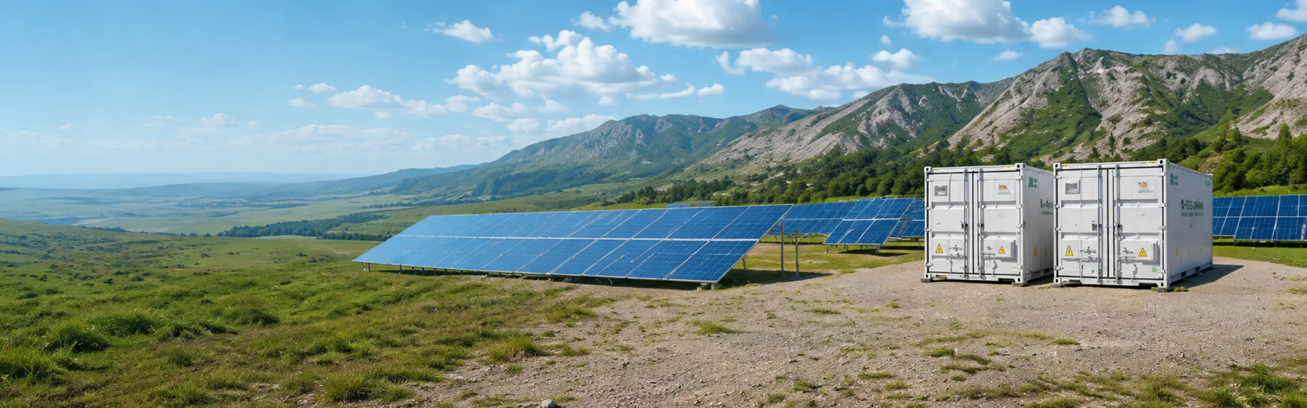
Bring us the project duty.
Share the required power and duration, electrical interface, site conditions and delivery scope.