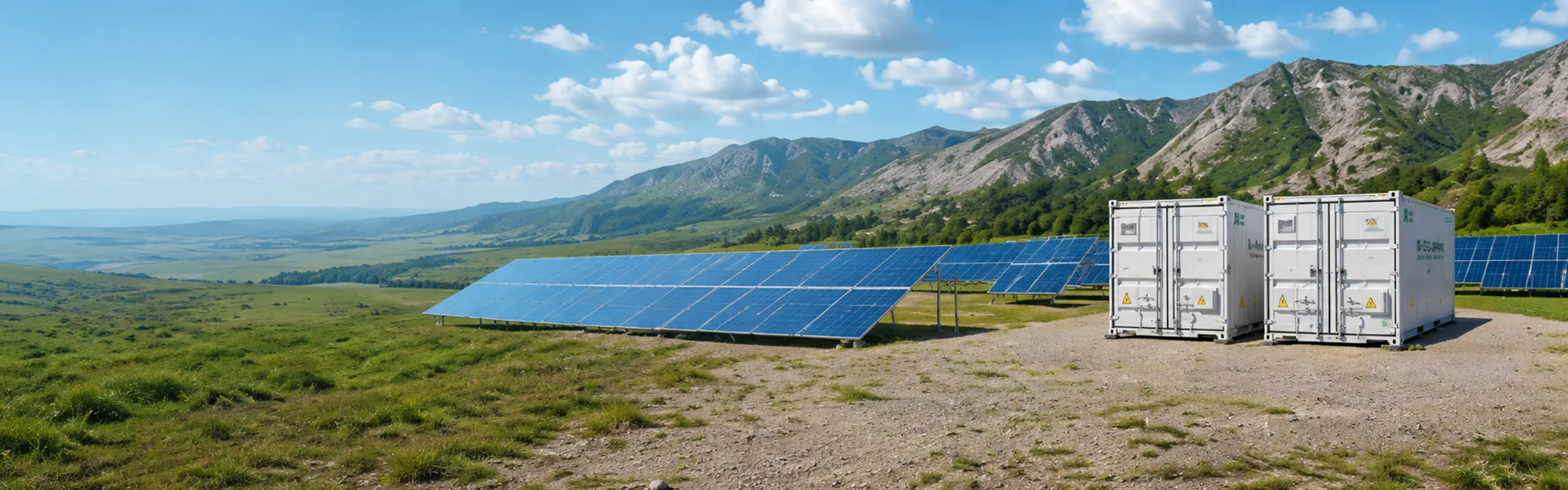
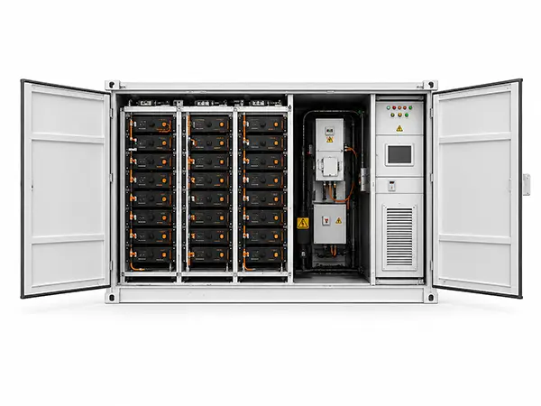
20-foot container and service environment
The container is an operating environment, not just a shell.
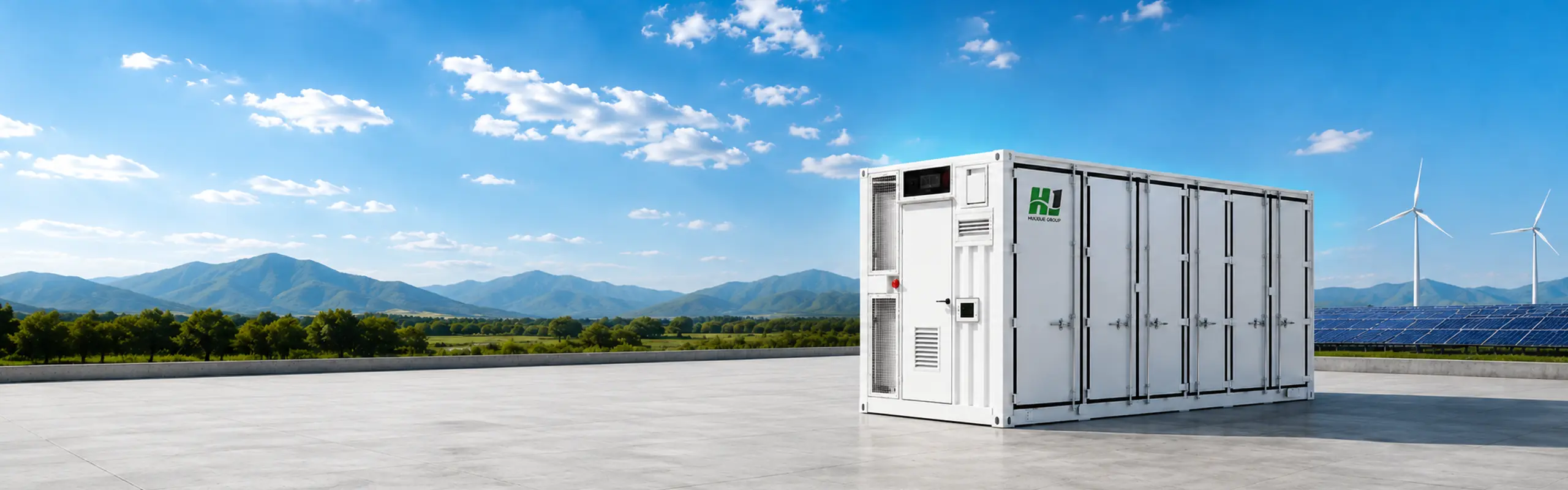
Higher density, more controlled cell temperatures. Configurable 2.5‑6.25 MWh 20‑foot platform for project‑specific power and duration.
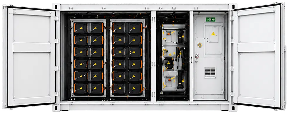
LFP cells are arranged into a monitored system; cell rating and series/parallel configuration vary across the reviewed family.
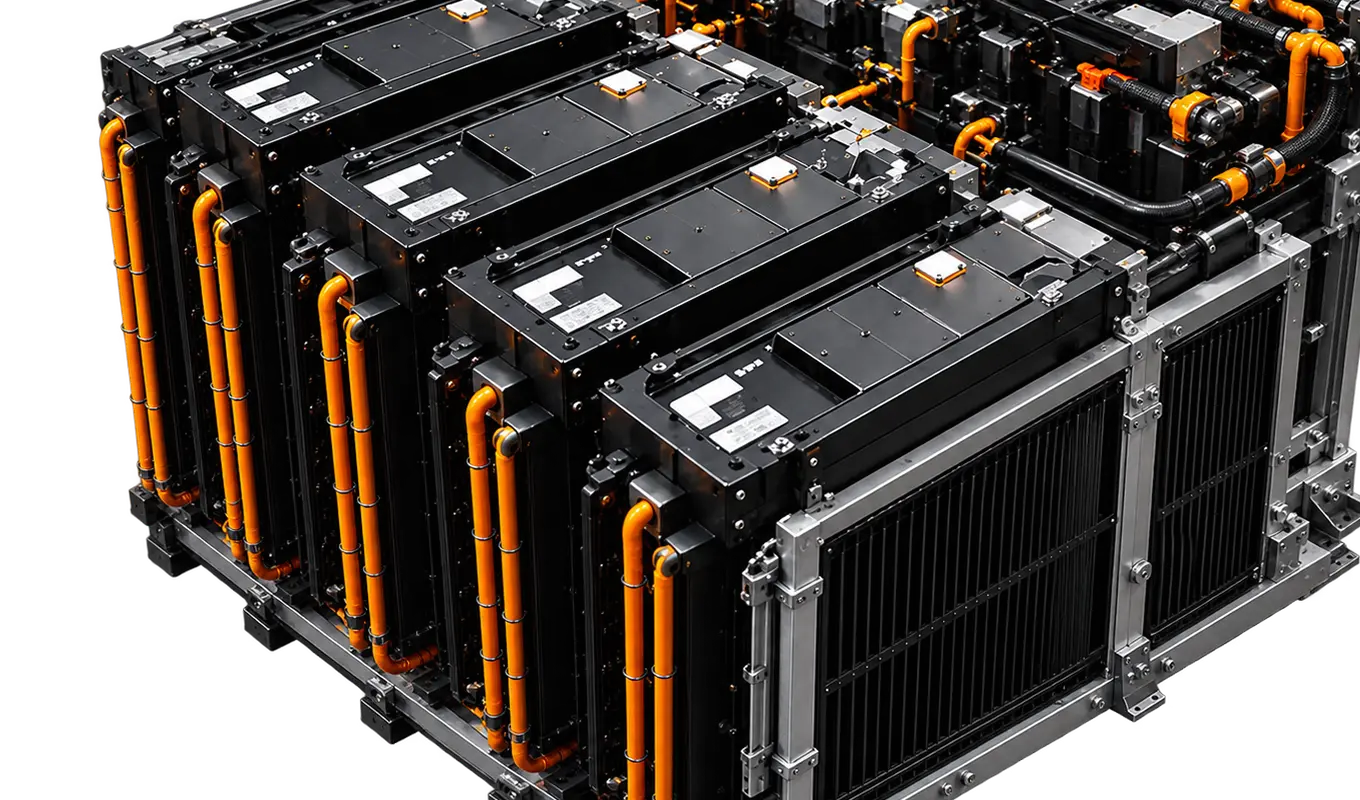
A working fluid circulates through the thermal circuit and transfers heat to a heat-rejection stage. Circuit design, coolant and operating limits are model-specific.
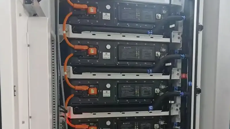
Schematic illustration
Define the DC block, power conversion and site connection. PCS, transformer, switchgear, EMS and site controls are confirmed for the selected project scope.
The container is an operating environment, not just a shell.
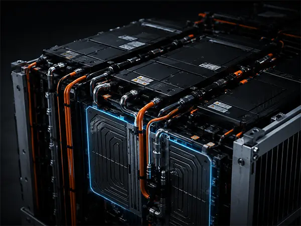
More energy, organized around the project duty.
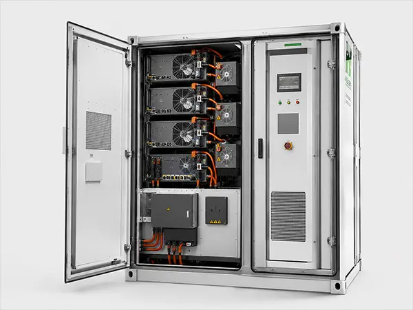
Capacity stores the energy. The power interface controls how it moves.
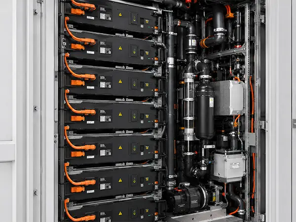
Cooling becomes part of the battery architecture.
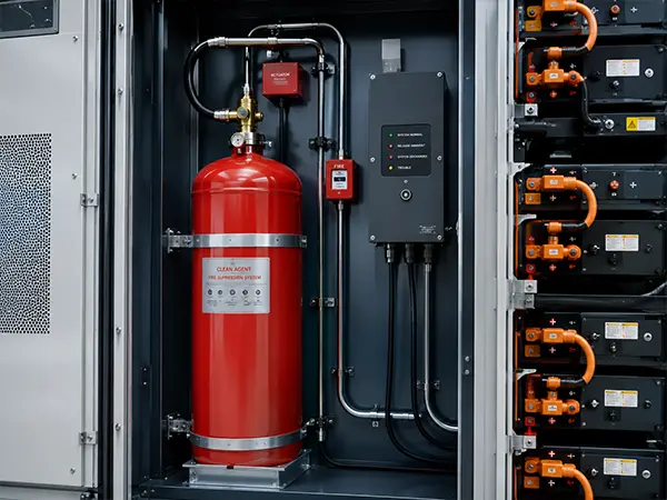
Safety is a sequence: detect, alert, isolate and respond.
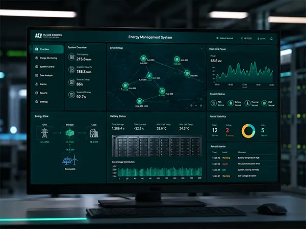
The BMS watches the battery from the inside out.
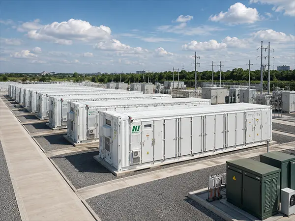
Local battery intelligence connects to the project control layer.
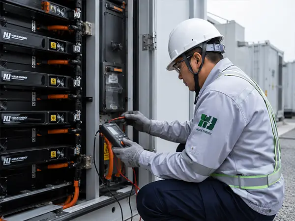
The system boundary continues beyond the battery container.
The final safety architecture and evidence set depend on model, integration scope, market and authority requirements.
Continuous cell-level and system-level monitoring through BMS and integrated sensors. Parameters are confirmed per model.
Gas detection, smoke detection and alarm systems provide early warning. Detectors and alert protocols are confirmed per model and market.
Electrical isolation at cell, module and system level. Isolation response and triggers are confirmed per model and AHJ requirements.
Fire-suppression equipment is included in reviewed configurations. Suppression medium, coverage and certification are confirmed per model and local regulation.
Continuous cell-level and system-level monitoring through BMS and integrated sensors. Parameters are confirmed per model.
Gas detection, smoke detection and alarm systems provide early warning. Detectors and alert protocols are confirmed per model and market.
Electrical isolation at cell, module and system level. Isolation response and triggers are confirmed per model and AHJ requirements.
Fire-suppression equipment is included in reviewed configurations. Suppression medium, coverage and certification are confirmed per model and local regulation.
Request the evidence package for the selected configuration and market.
UL 9540A is a test method. Results apply to the specific model, configuration and market — not a blanket certification claim.
BMS, system control and site communication interfaces are mapped to the selected integration scope. Modbus TCP/RTU · IEC 60870-5-104 · CAN — where supported by the selected model.
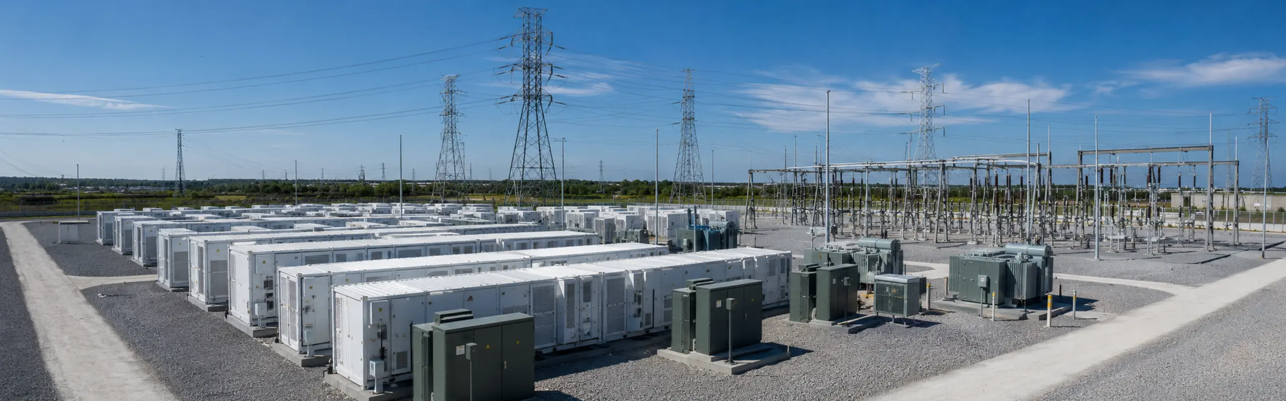
Utility and grid projects
Power and duration are coordinated with the grid interface and project-side equipment.
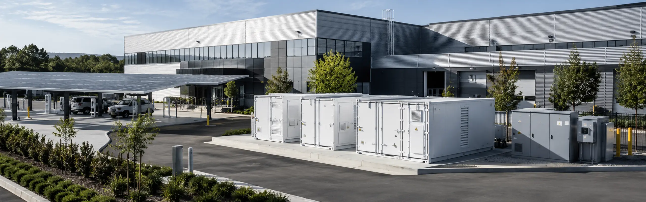
Industrial and commercial
The platform is configured around load profile, tariff strategy, footprint and operating conditions.
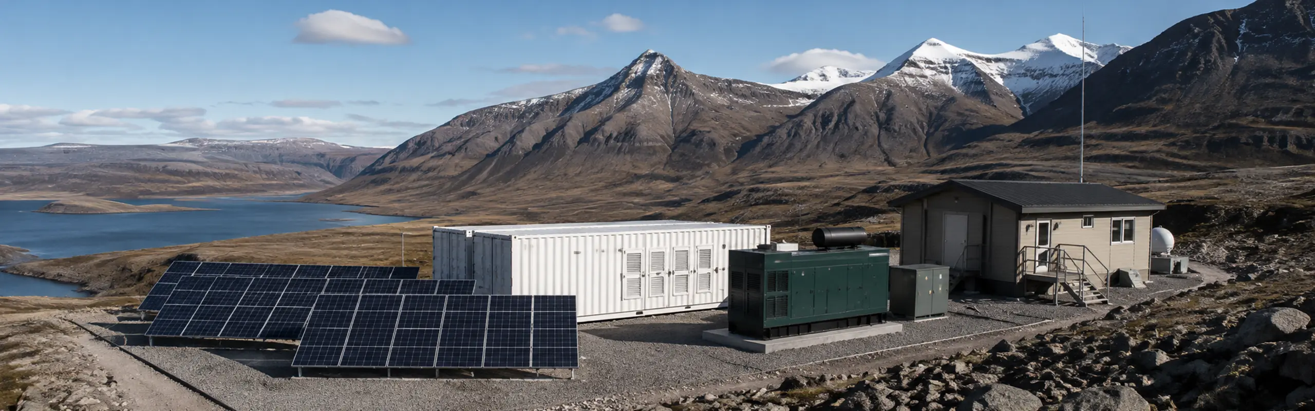
Microgrid and remote energy
Controls, generation sources and backup requirements define the integration scope.
| Specification | 2.5 MWh | 4.0 MWh | 5.0 MWh | 6.25 MWh / 1.725 MW | 6.25 MWh / 3.45 MW |
|---|---|---|---|---|---|
| Energy | 2.5 MWh | 4.0 MWh | 5.0 MWh | 6.25 MWh | 6.25 MWh |
| Rated power | 1.25 MW | 2.0 MW | 2.5 MW | 1.725 MW | 3.45 MW |
| Cell type | LFP 3.2 V / 314 Ah | LFP 3.2 V / 314 Ah | LFP 3.2 V / 314 Ah | LFP 3.2 V / 587 Ah | LFP 3.2 V / 587 Ah |
| Series / parallel | 6P416S | 12P416S | 12P416S | 8P416S | 8P416S |
| DC voltage | 1164.8–1497.6 V | 1164.8–1497.6 V | 1164.8–1497.6 V | 1164.8–1497.6 V | 1164.8–1497.6 V |
| Format | 20 ft | 20 ft | 20 ft | 20 ft | 20 ft |
| Cooling | Liquid cooling | Liquid cooling | Liquid cooling | Liquid cooling | Liquid cooling |
| IP rating | IP55 | Confirm | IP55 | IP55 | IP55 |
| Approx. weight | ≈30 t | ≈38 t | ≈45 t | ≈43 t | ≈43 t |
| Operating temp | −30°C to 55°C (derating >45°C) | −30°C to 55°C (derating >45°C) | −30°C to 55°C (derating >45°C) | −30°C to 55°C (derating >45°C) | −30°C to 55°C (derating >45°C) |
| PCS / transformer / switchgear | Confirm per project | Confirm per project | Confirm per project | Confirm per project | Confirm per project |
Note: The above content is for reference only. Customized solutions are available. Feel free to contact us for details.
From system integration and assembly to rigorous testing and delivery, our energy storage systems are built for real project requirements.
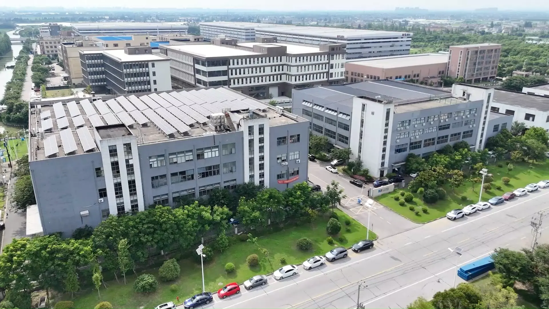
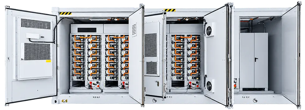
System Integration
Professional integration of battery, PCS, EMS and other core components.
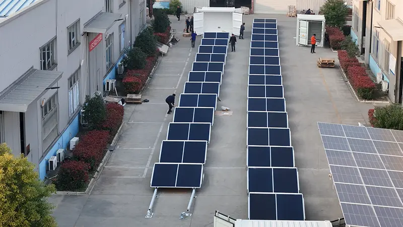
Assembly Process
Standardized assembly process ensures reliability and consistency.
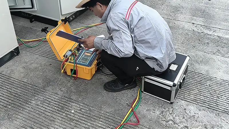
Quality Inspection
Multiple inspections at every stage to guarantee product quality.
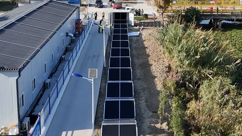
System Testing
Comprehensive functional, electrical and safety testing before delivery.
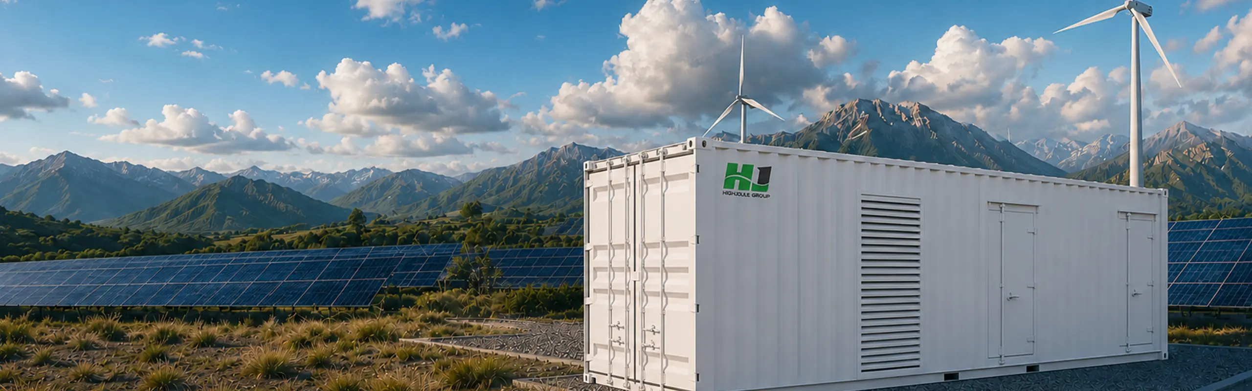
Finished Products
All systems are fully tested and ready for deployment.
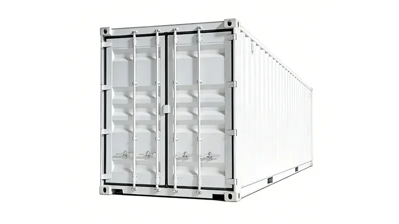
Delivery & Shipping
Secure packaging and efficient logistics to project sites.
A: A working fluid circulates through a thermal circuit near the battery equipment, carries heat to a heat exchanger and rejects it through the designed cooling stage. The exact coolant, circuit, redundancy and service procedure are model-specific.
A: Start with the required usable energy, target power, duration, duty cycle, site limits and delivery scope. The published energy rating alone does not determine the complete project configuration.
A: The reviewed records show the same published energy capacity with different rated output power. This indicates different power/duration duties, but nominal duration, losses, SOC window and operating limits must be confirmed by engineering.
A: Not by definition. The supply may be a DC block or an integrated configuration. The proposal must identify the location and responsibility for PCS, transformer, switchgear, controls and grid interface.
A: Use the current model-specific O&M manual to confirm coolant type, inspection points, service interval, leak checks, pump or heat-exchanger tasks, spares and access requirements. These details should not be generalized across the family.
A: Fire detection, alarm, isolation and suppression equipment must be confirmed for the selected model, market and authority requirements. Request the current system description and approved evidence package.
A: No assumption should be made. Certificates and test reports apply to defined models, configurations and markets. Review the current model-level evidence matrix before procurement.
A: Provide the load profile, target power and duration, charge/discharge duty, grid conditions, ambient range, altitude, site layout, access limits, fire-code context, communication requirements and delivery boundary.
Fill out the form below and our team will get back to you within 24 hours.
We'll help narrow the energy, power, duration and integration scope before technical review.