Container and service environment
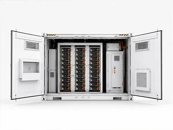
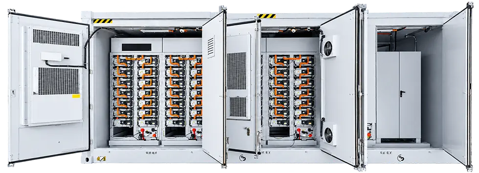
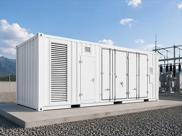
The container is an operating environment, not just a shell.
Project‑ready capacity with straightforward thermal management: a configurable 2.0‑5.0 MWh platform tailored to project‑specific power, duration and integration requirements.
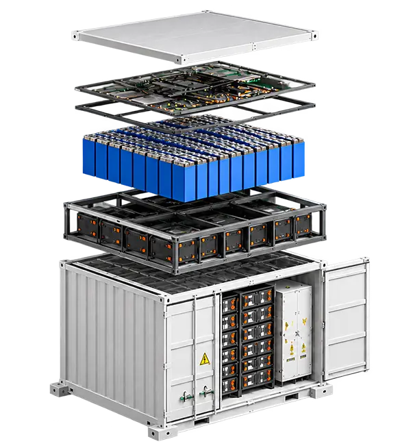
Starting at the cell level, LFP cells are assembled into a monitored battery system where the final series‑parallel arrangement is configuration‑specific and validated against reviewed model data.
Conditioned air, directed through the system, is distributed around the battery equipment by fans and air paths, with cooling capacity and ducting selected for the project's ambient temperature, altitude and duty profile.
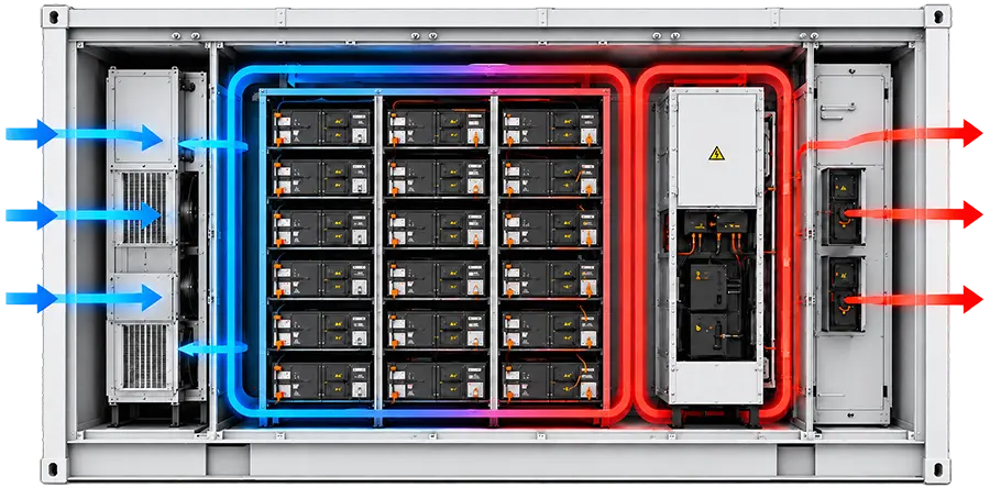
Schematic illustration
Define what arrives in the container — and what connects at site.
The container is an operating environment, not just a shell.
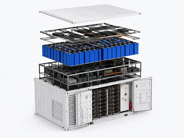
Energy begins at the cell—and becomes useful through the system around it.
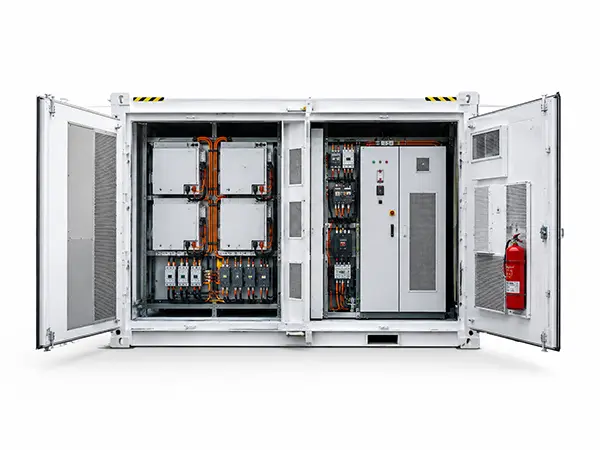
Capacity stores the energy. The power interface controls how it moves.
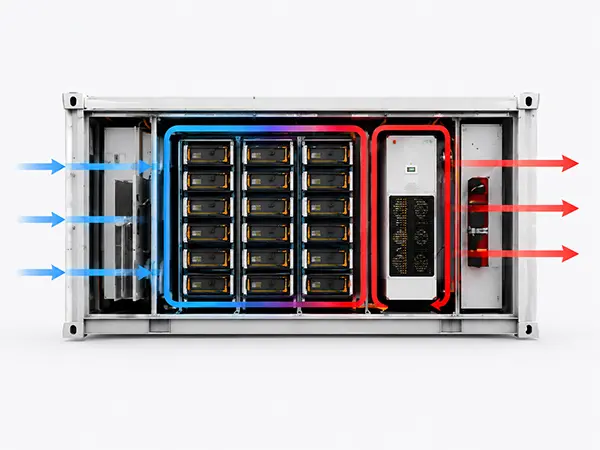
Conditioned air, directed through the system.
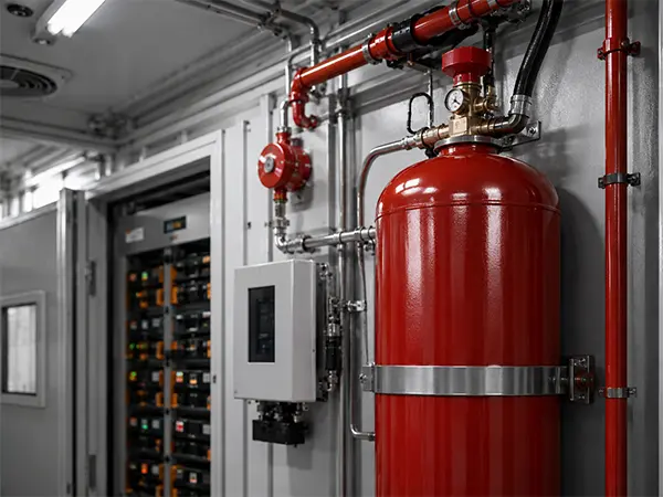
Safety is a sequence: detect, alert, isolate and respond.
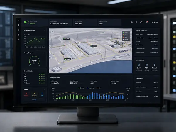
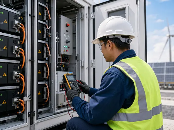
The BMS watches the battery from the inside out.
Local battery intelligence connects to the project control layer.
The system boundary continues beyond the battery container.
Detect, Alert, Isolate, Suppress — the four‑layer battery safety and fire‑protection system operates in sequence to prevent incidents, contain risks, and safeguard personnel and assets.
Continuous cell-level and system-level monitoring through BMS and integrated sensors.
Gas detection, smoke detection and alarm systems provide early warning.
Electrical isolation at cell, module and system level.
Fire-suppression equipment is included in reviewed configurations.
Continuous cell-level and system-level monitoring through BMS and integrated sensors.
Gas detection, smoke detection and alarm systems provide early warning.
Electrical isolation at cell, module and system level.
Fire-suppression equipment is included in reviewed configurations.
Request the evidence package for the selected configuration and market.
UL 9540A is a test method. Results apply to the specific model, configuration and market — not a blanket certification claim.
Visibility from cell status to site command.Battery monitoring, system controls and project communications are coordinated around the selected integration scope.
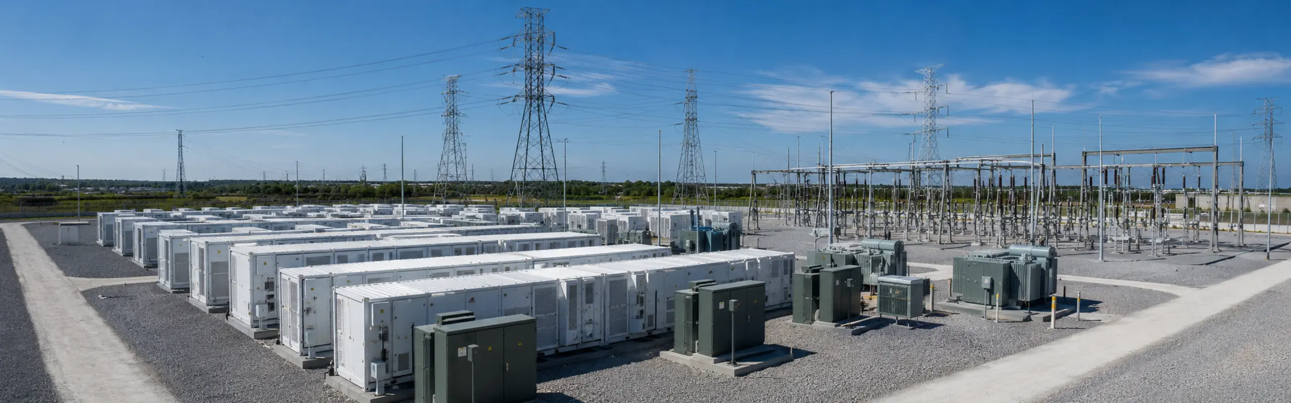
Utility and grid projects
Power and duration are coordinated with the grid interface and project-side equipment.
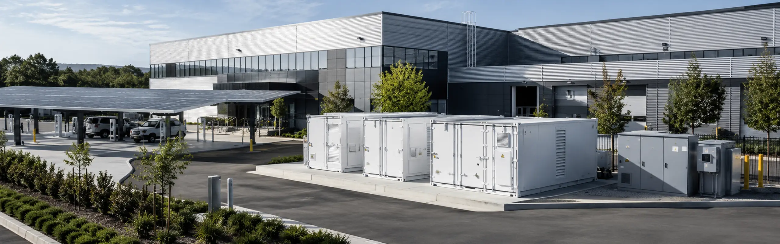
Industrial and commercial
The platform is configured around load profile, tariff strategy, footprint and operating conditions.
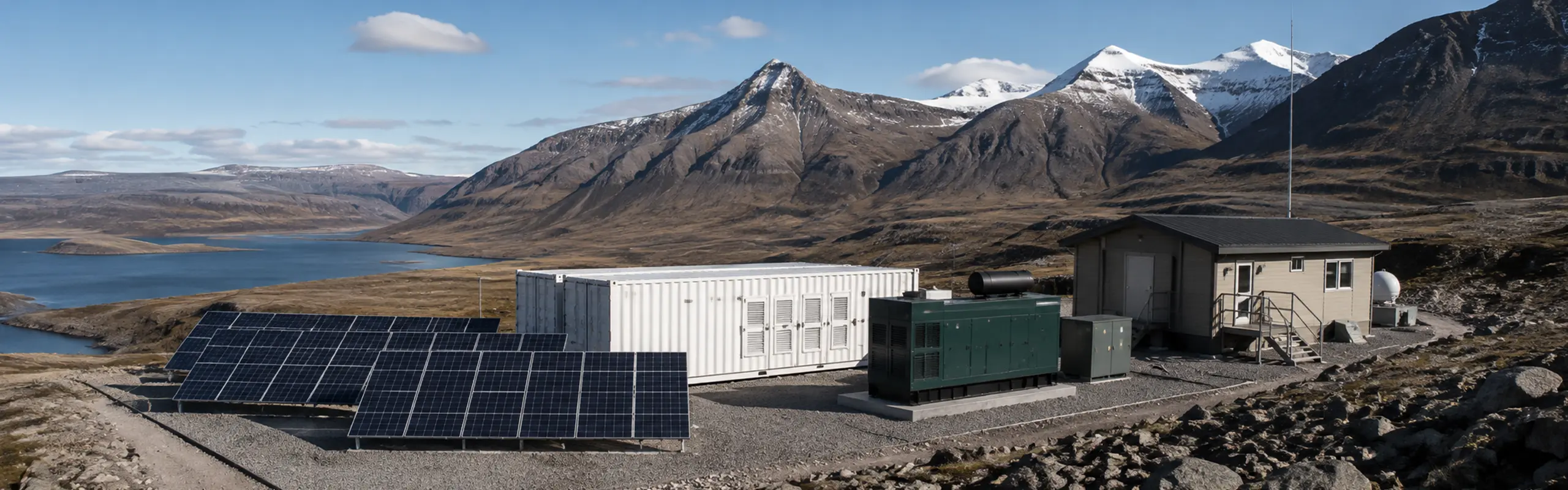
Microgrid and remote energy
Controls, generation sources and backup requirements define the integration scope.
| Specification | ≈2.0 MWh | 2.2 MWh | 2.4 MWh | 5.0 MWh |
|---|---|---|---|---|
| Energy | ≈2.0 MWh | 2.2 MWh | 2.4 MWh | 5.0 MWh |
| Rated power | Confirm | Confirm | Confirm per config | Confirm per config |
| DC voltage | Confirm | Confirm | Confirm | Confirm |
| Format | Primarily 40 ft | Primarily 40 ft | Primarily 40 ft | Primarily 40 ft |
| Cooling | Air-cooled | Air-cooled | Air-cooled | Air-cooled |
| IP rating | Confirm | Confirm | Confirm | Confirm |
| Chemistry | LFP | LFP | LFP | LFP |
| Operating temp | Confirm | Confirm | Confirm | Confirm |
Note: The above content is for reference only. Customized solutions are available. Feel free to contact us for details.
From system integration and assembly to rigorous testing and delivery, our energy storage systems are built for real project requirements.
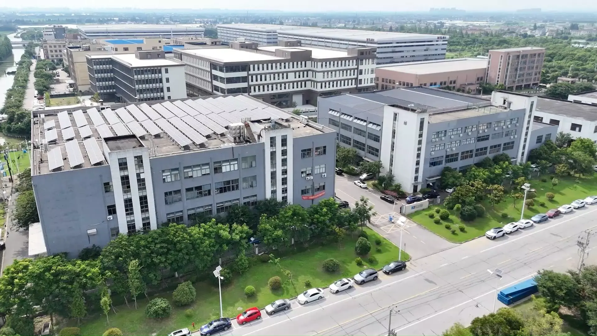
System Integration
Professional integration of battery, PCS, EMS and other core components.
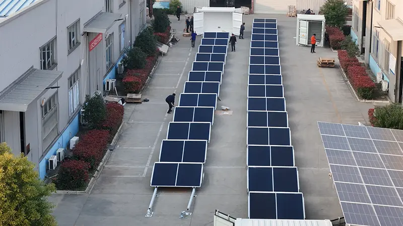
Assembly Process
Standardized assembly process ensures reliability and consistency.
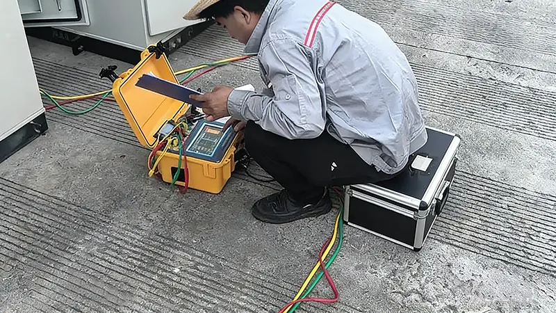
Quality Inspection
Multiple inspections at every stage to guarantee product quality.
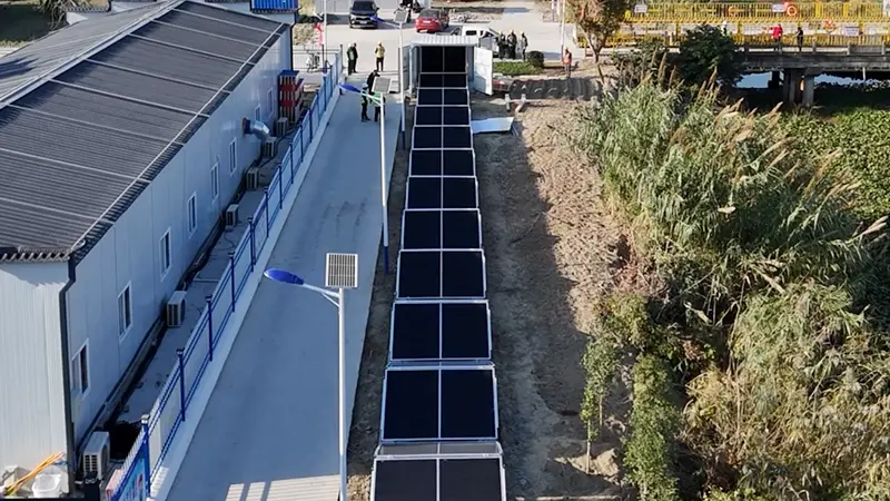
System Testing
Comprehensive functional, electrical and safety testing before delivery.
Finished Products
All systems are fully tested and ready for deployment.
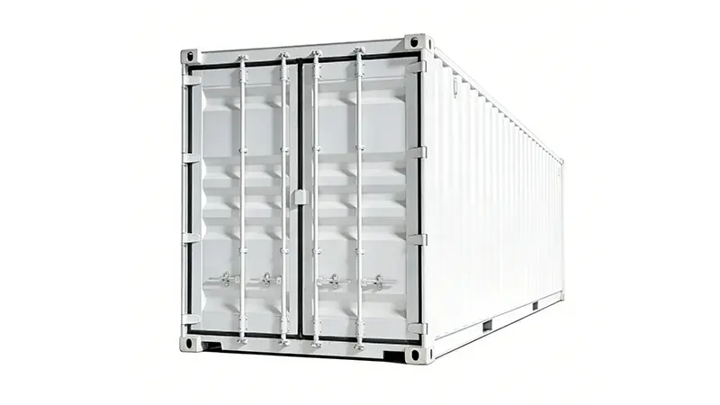
Delivery & Shipping
Secure packaging and efficient logistics to project sites.
A: Air-cooled systems distribute conditioned air with fans and designed air paths. Liquid-cooled systems circulate a working fluid through a dedicated thermal circuit. The right choice depends on duty cycle, ambient conditions, footprint, energy density requirements and maintenance preference.
A: It can be evaluated where the required capacity falls in the reviewed 2.0–5.0 MWh range, primarily 40 ft format is acceptable, site conditions support air-cooling (temperature, altitude, dust and humidity within operating limits), and maintenance access for air-handling equipment is feasible.
A: The reviewed configurations include battery system, BMS, thermal management and fire-detection equipment within the container. PCS, transformer, switchgear, EMS and site-level controls must be confirmed for each project scope — they are not included by default.
A: PCS and EMS appear in some reviewed integrated configurations, while transformer, switchgear and site controller scope varies by configuration. The proposal and scope sheet must explicitly state what is included and what remains project-side.
A: Certifications apply to the specific model, configuration, market and revision. Do not assume identical certification across all capacities. Request the evidence package for the selected configuration and authority having jurisdiction.
A: Maximum and minimum ambient temperature, altitude, solar exposure and shading, dust and corrosion environment, noise constraints, maintenance access dimensions and local fire and electrical codes.
A: Provide the load profile, required power and duration, grid interface, ambient and site conditions, footprint and access limits, required equipment scope, delivery destination and applicable compliance requirements.
Fill out the form below and our team will get back to you within 24 hours.
We’ll help narrow the capacity, power, duration and integration scope before technical review.