Off grid solar battery bank sizing comes down to three numbers: your daily energy consumption in kilowatt-hours, the number of consecutive days you need to operate without solar input, and your battery chemistry’s usable depth of discharge. Multiply daily kWh by autonomy days, then divide by usable DoD. That gives you the minimum rated capacity.
A residential cabin running 15 kWh per day with three days of autonomy on LiFePO4 batteries at 90% DoD needs roughly 50 kWh — about three server-rack batteries. A 200 kW mining camp consuming 3,800 kWh daily requires capacity in the multi-megawatt-hour range, distributed across several 20-foot containerized systems. The basic formula is the same. The scale changes everything else.
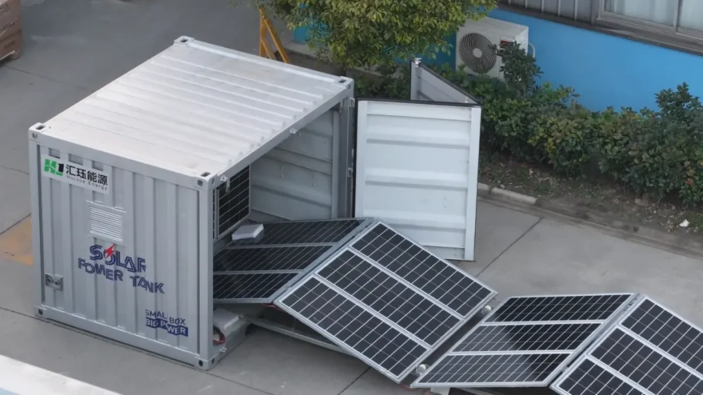
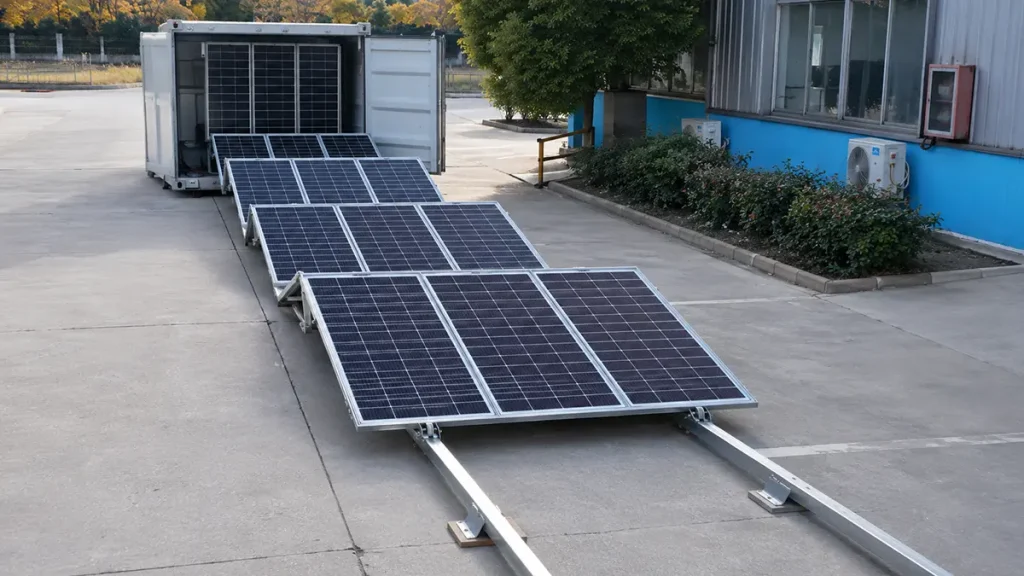
At industrial scale, the simple formula is a starting point, not the final answer. Temperature derating, load profile spikes, charge and discharge rate limits, system round-trip efficiency, and expansion headroom each shift the required capacity — sometimes by 30% or more. Our engineering team has designed and commissioned battery banks from a Maldives island resort powered by a 135 kWp PV array and a 261 kWh battery system to 46 kW foldable PV systems on Romanian construction sites, covering both the standard sizing formula and the industrial-scale factors that consumer guides skip.
For the complete site-level system design — PV array sizing, container selection, and deployment planning — see our off-grid solar container systems guide. This article focuses specifically on the battery bank sizing calculation.
Step 1: Load Audit for Industrial Sites
All battery sizing begins with a load audit. Homes only require tallying lights, fridges, HVAC and electronics, but industrial sites have far more critical loads. Missing equipment does not just cause inconvenience—it triggers costly downtime. For example, an unaccounted water treatment pump can drain batteries in hours, leaving generators to supply power alone.
Begin by cataloging every electrical device on site, grouped by priority tier. Tier 1 covers continuous essential loads: communications equipment, safety systems, monitoring electronics, and any process that cannot tolerate interruption. These draw power 24 hours a day and form the floor of your daily energy calculation. Tier 2 covers intermittent operational loads: water pumps, ventilation fans, workshop tools, lighting for occupied areas. These run on schedules — estimate daily runtime hours for each. Tier 3 covers surge loads: motor starts, crusher inrush current, welding equipment. These determine inverter sizing more than battery capacity, but affect the battery bank if sustained for minutes at a time.
For each device, record rated power in watts and estimated daily runtime in hours. Multiply to get watt-hours. A 15 kW water pump running 4 hours per day contributes 60 kWh. A 500 W communications rack running continuously adds 12 kWh. Sum everything to get total daily energy consumption in kilowatt-hours. For sites with seasonal variation — a mining camp that doubles occupancy in dry season, or a resort with peak air-conditioning load in summer — run the audit for the worst-case month. Sizing for the average month leaves you short when it matters.
Step 2: Choosing Autonomy Days
Days of autonomy is the number of consecutive sunless days your battery bank must cover before the site runs out of power. In any off grid solar battery bank sizing exercise, this variable drives the result more than any other factor. Choosing it incorrectly is the single most expensive mistake we see in third-party RFQs.
| Application | Typical Autonomy | Rationale |
| Telecom tower (grid-backup) | 1-2 days | Grid typically restores within hours; battery bridges the gap |
| Mining camp (with diesel backup) | 3-4 days | Cloud cover during wet season; generator covers extended shortfall |
| Island resort (full off-grid) | 2-3 days | High solar resource; generator available for unusual weather |
| Emergency/disaster relief | 3-5 days | No resupply window after deployment; must ride through worst-case event |
| Remote research station with generator or wind backup | 5-7 days | Battery covers short-term low-generation periods; generator or wind generation is required during extended polar darkness |
In practice, however, we often see clients arrive with a fixed “three days” assumption. After reviewing site-specific solar irradiance data and generator availability, the realistic autonomy requirement may drop from three days to two — cutting the battery bank cost by roughly a third when the site conditions support that design choice. The European Commission Joint Research Centre publishes PVGIS solar resource datasets that provide a useful starting point for pre-feasibility work.
European Commission PVGIS solar resource tool — free solar irradiance data and PV yield estimates for preliminary sizing work.
Step 3: The Core Calculation — Off Grid Solar Battery Bank Sizing Formula
Once you have daily energy consumption and autonomy days, the core formula gives an initial capacity estimate:
Rated battery capacity (kWh) = Daily consumption (kWh/day) × Autonomy days ÷ Depth of Discharge
For a mining camp consuming 800 kWh per day with 3 days of autonomy and LiFePO4 batteries allowing 90% DoD: 800 × 3 ÷ 0.90 = 2,667 kWh of rated capacity. This is the starting number. At 48V nominal, this converts to roughly 55,600 Ah — which is why industrial systems use higher DC voltages to keep current and cable sizing practical.
Consumer-oriented guides often stop here. For a containerized BESS, however, you need at least four adjustments before an off grid solar battery bank sizing calculation becomes actionable: temperature derating, C-rate limits, system efficiency losses, and module granularity.
Adjustment 1: Temperature Derating
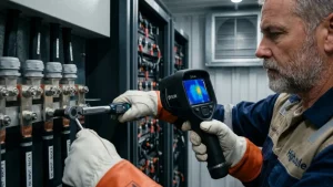
LiFePO4 cells deliver rated capacity at 25°C. At 0°C, usable capacity drops to roughly 80-85% of rated; at -20°C, expect 60-70% without active thermal management. These figures come from cell manufacturer specification sheets and align with our test data across multiple projects in extreme environments. Our systems use liquid cooling with integrated heating to maintain cell temperature within 15-35°C across ambient conditions from -30°C to 50°C. If your battery bank uses passive cooling, apply the manufacturer’s derating curve — a 3,000 kWh bank at -20°C ambient may only deliver roughly 2,000 kWh unless heating is active.
Adjustment 2: Charge and Discharge Rate (C-Rate)
Battery capacity is specified at a standard discharge rate — typically 0.5C, meaning the full rated energy is delivered over two hours. If your load profile demands higher discharge rates, effective capacity decreases. For sustained discharge rates approaching or exceeding the cell manufacturer’s continuous C-rate limit, additional capacity or parallel strings may be required. In several of our evaluated configurations, this resulted in a 10-15% capacity margin, although the final value is cell- and duty-cycle-specific. Liquid-cooled container systems handle high C-rates better than passively cooled racks because cell temperature remains within the optimal band under sustained load.
Adjustment 3: System Efficiency Losses
The core formula assumes 100% round-trip efficiency, which no real system achieves. Based on commissioning measurements at the DC bus, excluding downstream AC distribution losses, our DC-coupled container systems have demonstrated approximately 92-95% round-trip efficiency under rated operating conditions. AC-coupled architectures add inverter losses at each conversion stage. For a 2,667 kWh calculated requirement, applying a conservative 0.92 efficiency factor pushes the required capacity to approximately 2,900 kWh before considering other adjustments.
Adjustment 4: Module Granularity
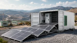
Container BESS systems ship in discrete modules. Each 20-foot container in our HJ-FBESS series accommodates multiple battery blocks — the exact count and total capacity depend on the configuration and system voltage. If your adjusted requirement is roughly 2,900 kWh, you round up to the next available container configuration, not down. A 5-10% buffer is less expensive than retrofitting additional capacity two years later.
Hybrid Generator and Battery Sizing
Many industrial off-grid sites do not run on 100% solar and battery. A diesel or gas generator handles the worst-case days, and the battery bank covers normal operation. This hybrid architecture changes the battery bank sizing calculation significantly.
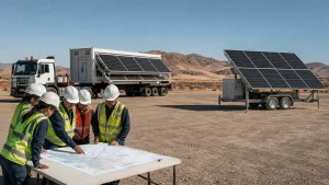
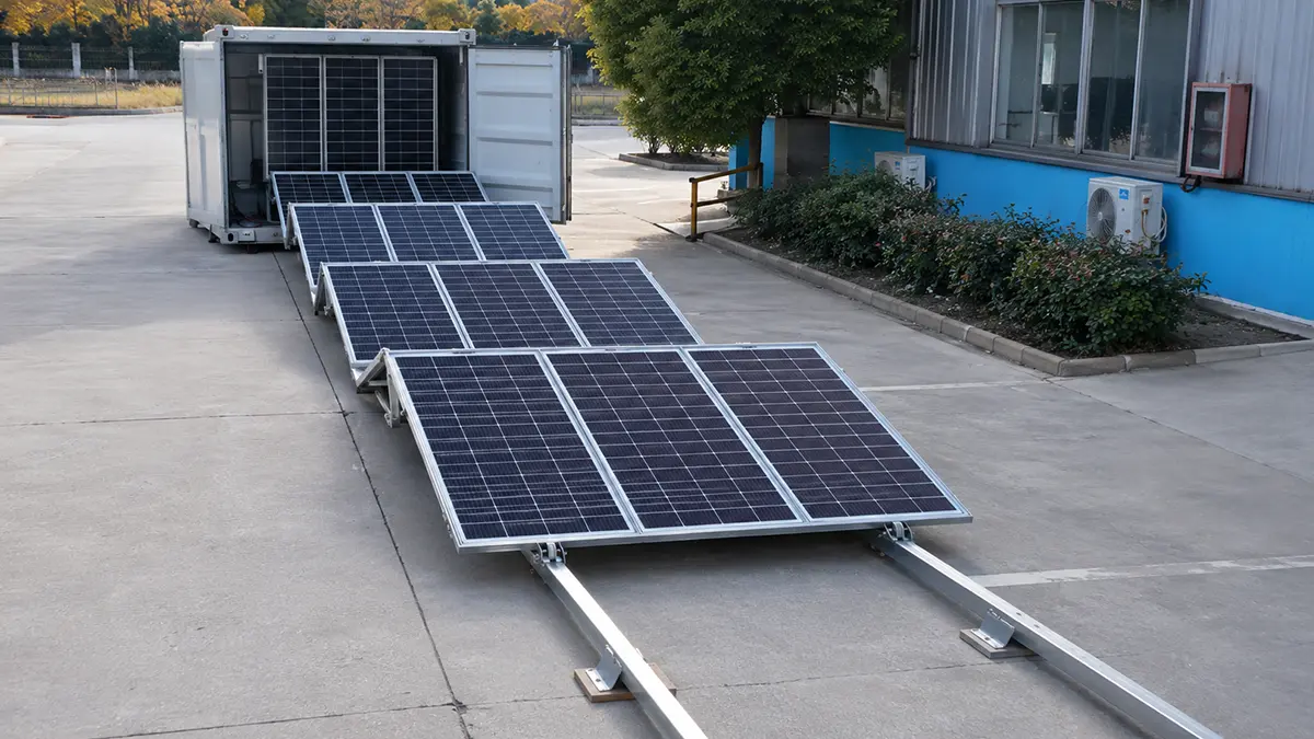
Instead of sizing for the worst-case weather scenario, you size for the “generator trigger threshold” — the point at which the control system starts the generator. For a site with a 100 kW generator and 250 kW peak load, the battery handles the gap between generator output and peak demand, plus the normal daily solar-battery cycle. A realistic hybrid configuration for a 500 kWh/day site might use around 800 kWh of battery with a 150 kW generator, rather than approximately 2.8–3.0 MWh of battery for five days of battery-only autonomy. Our Romania deployment uses this approach: four foldable PV arrays paired with 184 kWh of storage and a diesel generator for extended low-irradiance periods.
Reference Table: Indicative Industrial Configurations
The table below shows typical sizing ranges based on project data from our deployments. These are indicative — your specific site conditions will shift the numbers. Battery capacity figures assume LiFePO4 chemistry with 90% DoD and include efficiency derating. For a step-by-step walkthrough of the calculation, refer to the off grid solar battery bank sizing method in the preceding sections.
| Application | Typical Daily Load | Autonomy | Approx. Battery Capacity | Container Footprint |
| Telecom BTS (remote) | 50-80 kWh | 2 days | 120-200 kWh | 1 × compact container |
| Construction site camp | 200-400 kWh | 2 days | 480-960 kWh | 1-2 × 20ft |
| Mining camp (~150 person) | 800-1,200 kWh | 3 days | 2,900-4,300 kWh | 2-3 × 20ft |
| Island resort (50 bungalow) | 300-500 kWh | 2-3 days | 720-1,800 kWh | 1-2 × 20ft |
| Emergency field hospital | 150-250 kWh | 3 days | 540-900 kWh | 1-2 × 20ft |
| Industrial microgrid | 1,500-3,000 kWh | 2-3 days | 3,600-10,800 kWh | 3-6 × 20ft |
In our Maldives project, a 135 kWp PV array paired with 261 kWh of storage serves a resort operating at approximately 400 kWh per day. The battery alone provides roughly 14 hours of coverage at the stated average load. With daytime PV generation contributing during daylight hours, the system sustains continuous operation under typical solar conditions at that latitude. This real-world configuration illustrates why off grid solar battery bank sizing must account for the interplay between PV generation profile, load curve, and battery capacity — not a single formula in isolation.
Common Sizing Mistakes We See in RFQs
Across the client RFQs reviewed by our engineering team, four errors appear more often than any others. Spotting these early can save weeks of redesign.
Mistake 1: Ignoring seasonal irradiance variation. European Commission PVGIS data for Bucharest, Romania (44.43°N, fixed array at 35° tilt) estimates plane-of-array irradiation at about 5.54 kWh/m²/day in April and 2.02 kWh/m²/day in December — roughly 64% lower. Other sites near 45°N can differ materially because of local climate, array tilt, terrain shading, snow cover, and weather patterns. Always use the lowest monthly insolation figure for the sizing calculation — not the annual average.
Mistake 2: Confusing inverter kW with battery kWh. Inverter rating determines peak power delivery capability. Battery capacity, in contrast, determines energy storage duration. A 250 kW inverter paired with 250 kWh of battery can deliver full power for only one hour. These numbers serve different functions.
Mistake 3: Omitting round-trip efficiency and auxiliary loads. DC-coupled container BESS typically achieves 92-95% round-trip efficiency at the DC bus, based on our commissioning measurements and excluding downstream AC distribution losses. The battery management system, thermal management, and controls draw continuous auxiliary power. Auxiliary consumption varies with ambient temperature and operating mode. In our measured projects, thermal management, BMS, controls, and fire-safety auxiliaries consumed approximately 1-3% of nominal battery capacity per 24-hour period under the specified operating conditions. Tropical daytime cycling and sub-zero heating represent opposite ends of this range. Both factors must be included in the sizing calculation.
Mistake 4: Sizing for today’s load with no expansion path. Industrial sites grow. A mining camp that starts at 150 personnel may expand to 250 within two years. Modular container BESS systems provide the most practical expansion path: add a container module when load grows, rather than over-investing in capacity that sits idle for the first 18 months.
Get a Project-Specific Sizing Assessment
The methods in this guide provide a solid starting point for battery bank sizing at industrial scale. For a project-specific recommendation backed by your site’s solar irradiance data, load profile, and ambient temperature range, our engineering team provides a detailed assessment at no cost for qualified projects.
About the Authors
Shanghai HighJoule Energy Technologies Ltd. designs and manufactures containerized solar battery energy storage systems in Shanghai, China. Our HJ-FBESS and HJ-FESS series have been deployed in more than 20 countries on four continents — from a 4,500 m Tibetan Plateau microgrid to a 135 kWp PV and 261 kWh battery system for an island resort in the Maldives, from Ukrainian emergency power installations to Romanian construction site hybrid systems. For a complete overview of configurations and technical specifications, visit our HJ-FBESS solar container.
Our products have been tested in accordance with UL 9540A (thermal runaway propagation test), and comply with GB/T 36276, IEC 62933 series, and CE marking requirements for multi-jurisdiction deployment. Certification details vary by product model and configuration — contact our team for the specific certificates applicable to your project.
This article draws on sizing data and commissioning measurements from our project portfolio. Customer identities and precise site locations have been anonymized where required by confidentiality agreements.
References and Engineering Notes
The following sources informed the data and methodology in this article:
Solar resource data: IRENA Global Atlas for Renewable Energy (irena.org); NREL National Solar Radiation Database (nsrdb.nrel.gov); European Commission PVGIS monthly irradiation calculator for the Bucharest example.
Cell temperature derating: Based on LFP cell manufacturer specification sheets for prismatic cells rated at 280-314 Ah, cross-referenced with HighJoule in-house thermal chamber test data (2024-2025).
Round-trip efficiency: Measured at the DC bus during factory commissioning tests on HJ-FBESS container systems, rated operating conditions, excluding downstream AC distribution and transformer losses.
Auxiliary consumption: Measured across representative operating modes and ambient conditions in commissioned projects. Values are indicative and project-specific.
C-rate margin: Derived from cell manufacturer continuous discharge ratings and system-level evaluation across several project configurations. Margin is configuration-specific and not a universal design rule.
Certification and compliance: UL 9540A thermal runaway propagation test reports; GB/T 36276, IEC 62933 series, and CE marking documentation — applicable model and configuration list available on request.
Disclaimer: The sizing figures in this article are indicative and based on our project experience. Actual battery bank sizing depends on site-specific solar resource data, load profiles, ambient temperature conditions, and local regulatory requirements. Always consult a qualified engineer for project-specific sizing. Battery capacity figures assume LiFePO4 chemistry at standard test conditions (25°C, 0.5C discharge) unless otherwise noted.
Last Updated on 07/30/2026