BESS Thermal Management Is a Site Decision
BESS thermal management is often reduced to a simple claim: liquid cooling is advanced and air cooling is basic. That is not a useful way to specify a container battery energy storage system. The right choice depends on heat load, ambient temperature, battery density, duty cycle, dust and humidity exposure, and the maintenance capability available at the site.
For the wider electrical and safety context, start with our Container BESS Engineering Guide. This article focuses on the thermal-management decision inside a container: when air cooling is reasonable, when liquid cooling is easier to defend, and what evidence a buyer should request before signing an RFQ.
Air cooling can be a practical choice for lower-density systems in temperate locations with modest cycling and an accessible maintenance team. Liquid cooling becomes more compelling when a project combines dense battery packaging, high ambient heat, repeated charge-discharge cycles, or remote operation where uneven cell temperature can become a reliability problem. Neither architecture removes the need for proper BMS controls, sensors, maintenance, and site-specific engineering.
Step 1: Define the BESS Thermal Management Inputs Before Comparing Equipment
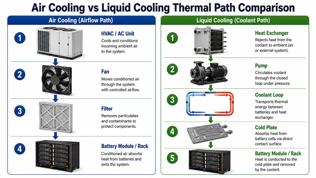
Every battery creates heat during charging, discharging, standby operation, and exposure to the surrounding environment. A container adds another layer: solar gain on the enclosure, limited air volume, nearby power electronics, cable losses, and the heat rejected by cooling equipment. BESS thermal management begins with that complete heat path. A brochure that only says “liquid cooled” does not explain whether the thermal path is appropriate for your duty cycle.
Begin with five project inputs for BESS thermal management. First, define the daily load profile and the expected charge-discharge rate. Second, record site temperature, humidity, solar exposure, altitude, and the difference between day and night conditions. Third, confirm how densely the battery modules will be arranged inside the enclosure. Fourth, identify dust, salt fog, sand, or condensation risk. Finally, decide who will inspect filters, pumps, coolant connections, sensors, and alarms after commissioning.
This sequence matters because the same nominal energy capacity can behave differently in two locations. A 261 kWh cabinet that cycles gently in a shaded, temperate service yard is not facing the same thermal task as a similar unit supporting a coastal resort, a desert pump station, or a remote mine where daytime charging and evening discharge are both demanding.
Step 2: Understand the Thermal Path Inside a Container
How air cooling works
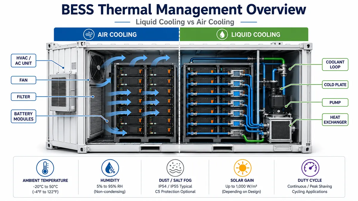
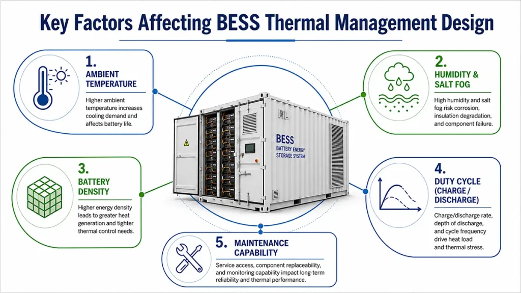
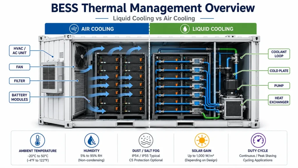
An air-cooled BESS uses fans, ductwork, HVAC equipment, or a combination of these to move conditioned air across battery modules and power electronics. It is familiar to many maintenance teams. Filters, fans, coils, and airflow paths are visible and conceptually simple. The architecture can be effective where heat generation is modest, the ambient climate is manageable, and equipment can be inspected regularly.
Air cooling is not inherently unreliable. The practical limitation is temperature distribution under the project’s actual airflow path. Dust loading, blocked filters, recirculation, enclosure layout, and uneven rack loading can all reduce airflow where it is needed. In a dense container, the average temperature can look acceptable while some cells or modules experience a less favorable condition. Ask the supplier to demonstrate the temperature-measurement method for the proposed layout.
How liquid cooling works
A liquid-cooled BESS moves heat through a controlled coolant loop. Depending on the design, cold plates, thermal channels, piping, pumps, valves, a heat exchanger, and a cooling unit transfer heat away from cells and modules. This BESS thermal management approach then rejects heat outside the battery compartment. It adds components and maintenance tasks, but it can offer more direct control of temperature distribution in high-density layouts.
Liquid cooling is not maintenance-free. Procurement teams should ask about coolant type, fill and service procedure, pump redundancy where relevant, leak detection, hose and fitting inspection, alarm logic, and the service interval for the cooling unit. A good system design makes these tasks visible in the maintenance plan instead of treating them as an afterthought.
| Decision factor | Air-cooled architecture | Liquid-cooled architecture | Evidence to request |
| Heat transfer path | Conditioned air, fans, ducts, HVAC flow | Coolant loop, cold plates or channels, heat exchanger | System drawing showing the heat path and sensor locations |
| Best-fit conditions | Lower density, moderate climate, accessible maintenance | Dense systems, high heat exposure, frequent cycling, constrained space | Site duty-cycle and ambient-condition assumptions |
| Typical routine work | Filter, fan, coil, airflow and HVAC inspection | Cooling-unit, pump, valve, coolant, sensor and leak-monitoring inspection | O&M schedule, spare-parts list, local service route |
| Dust sensitivity | Filter condition and airflow restriction need close attention | Enclosure and external heat rejection still need protection; loop condition also matters | Ingress-protection basis and cleaning procedure |
| Temperature uniformity | Depends strongly on airflow path and rack layout | Can provide closer control when the loop and plates are correctly designed | Test condition, sensor map, duration, and calculation method |
Step 3: Conditions Where Air Cooling Still Fits
Air cooling still has valid applications. A lower-density C&I system in a moderate climate may not need the added complexity of a liquid loop. If the system cycles at modest rates, has adequate ventilation space, and sits near a service team that can maintain filters and HVAC equipment, an air-cooled design may offer a sensible balance of capital cost, simplicity, and serviceability.
It can also be appropriate where battery capacity is spread across multiple smaller cabinets rather than packed into a compact container. In that configuration, more enclosure surface area and lower local heat concentration can make airflow management easier. The decision should be based on measured or modeled operating conditions, not on the assumption that every project needs the same architecture.
For a buyer, liquid cooling should not be specified merely because it sounds more premium. If the site has benign conditions and the maintenance team knows the HVAC platform, air cooling can be the more proportionate solution. The BESS thermal management decision should still include high-ambient-temperature behavior and derating when airflow is restricted or filters require service.
Step 4: BESS Thermal Management Conditions Where Liquid Cooling Is More Defensible
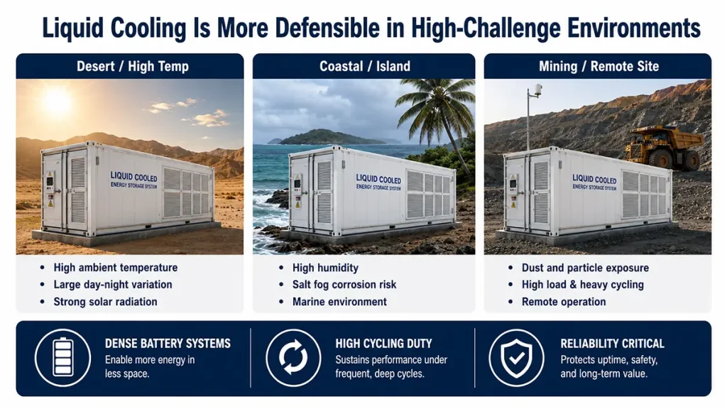
The argument for a liquid-cooled design strengthens when several risks appear together: high ambient temperature, frequent cycling, a compact battery layout, constrained space, and limited on-site technical support. In those conditions, BESS thermal management may benefit from a controlled liquid loop that reduces dependence on long air paths and supports a more even temperature across the battery system. The supplier should substantiate that conclusion for the proposed cooling unit, sensor arrangement, and operating profile.
For industry background on why larger BESS containers increasingly use liquid temperature control, see Solar Power World’s 2025 review of BESS temperature control. The article is context only; each project still requires its own thermal calculation and acceptance evidence.
Remote industrial sites are a common example. Sand and dust can increase the maintenance burden on any outdoor system. High humidity and salt fog add corrosion and condensation concerns. A liquid-cooled enclosure does not make those risks disappear, but it allows the thermal design to rely less on moving large volumes of outdoor air through the battery area. The enclosure, heat-rejection equipment, cable entries, and service procedures still need to match the environment.
Container systems also concentrate multiple functions: batteries, a power conversion system (PCS), battery management system (BMS), energy management system (EMS), safety equipment, and sometimes PV integration. The practical question is not “liquid or air?” in isolation. It is whether the entire container can maintain safe, stable operation as the battery, power electronics, and environment interact over the project life.
For a factory-integrated container option, review the HJ-FBESS solar container platform alongside the RFQ evidence in this article. Request the proposed sensor map, cooling-maintenance schedule, high-ambient derating logic, and FAT/SAT test points for your actual load and site environment.
Project Evidence: A Coastal Liquid-Cooled Site
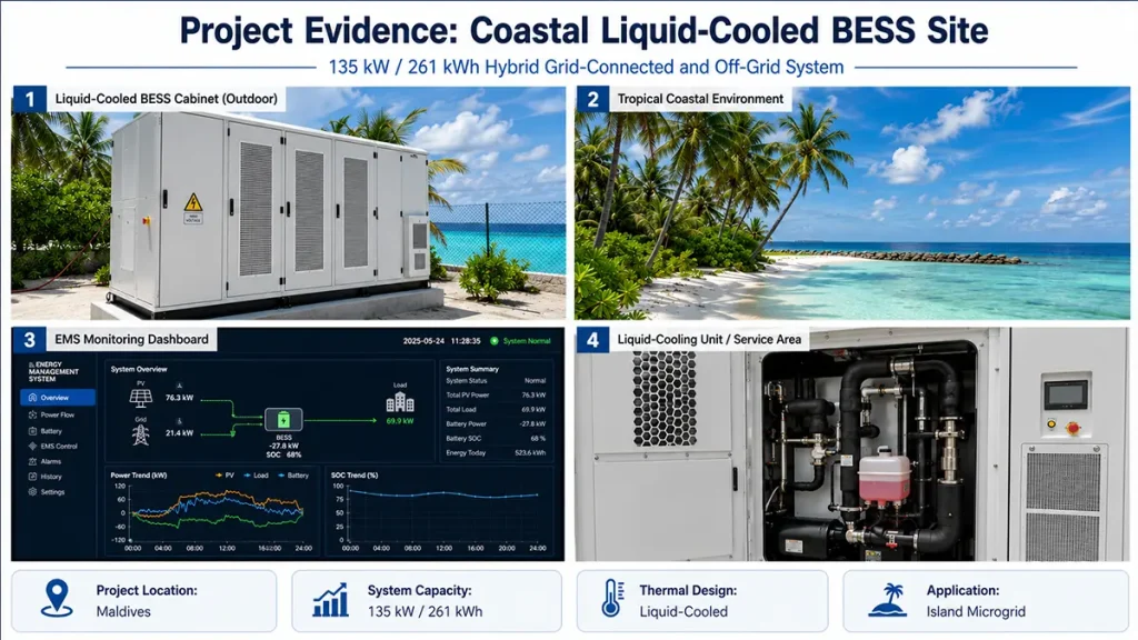
The Maldives 135 kW/261 kWh Hybrid Grid-Connected and Off-Grid Liquid-Cooled Energy Storage System Project is a useful reference because its design problem was broader than energy capacity. The beach-tourism location needed support for growing business load, grid insufficiency, and sudden outages while operating in a high-humidity, salt-fog environment.
The public project record specifies 135 kWp PV, 135 kW rated storage power, and 261 kWh of lithium iron phosphate (LiFePO4) storage. It uses an outdoor-rated cabinet with IP55 protection and C4-grade corrosion resistance. The project page describes a 5 kW precision liquid-cooling unit and a stated cell-temperature-difference target of no more than 3°C. It does not publish the corresponding sensor map, ambient condition, duty cycle, or test duration. Buyers should request those test boundaries before comparing that value with another system. These details apply to the documented configuration and are not a universal performance promise for every container or climate.
The important point is the engineering logic behind the configuration. Coastal humidity, salt exposure, compact space, variable tourism demand, and the need to change between grid-connected and off-grid modes make BESS thermal management part of a wider availability plan. The liquid-cooling unit, EMS, corrosion measures, enclosure protection, and maintenance pathway have to work as one system.
Step 5: Put BESS Thermal Management Into the RFQ and Acceptance Test
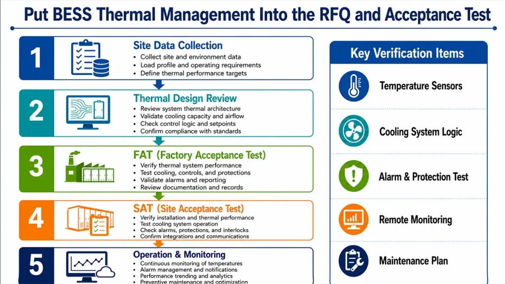
The cooling architecture should be testable before the system arrives on site. Make BESS thermal management a named part of the factory acceptance test (FAT) and site acceptance test (SAT), rather than a line item hidden in the general specification. The goal is not to force one technology. It is to make sure the chosen approach has evidence behind it.
- Define the operating envelope. State the ambient-temperature range, humidity, altitude, solar exposure, dust or salt-fog exposure, charge-discharge profile, and expected operating schedule. The supplier cannot design a credible thermal strategy from a single annual average temperature.
- Request a temperature-measurement method. Ask where sensors are placed, how cell or module temperature spread is calculated, what conditions are used for the test, and which alarms or derating actions follow an out-of-range result.
- Separate battery temperature from enclosure temperature. A comfortable container air temperature does not by itself demonstrate uniform cell conditions. The RFQ should distinguish cell, module, rack, and enclosure measurements.
- Ask how auxiliary energy is counted. Cooling, BMS, controls, fire-safety equipment, and container auxiliaries consume energy. Their contribution varies with ambient conditions and operating mode. Ask the supplier to identify the measurement boundary rather than quoting a single efficiency value without context.
- Ask for a service and failure-response plan. For air cooling, confirm filter and HVAC maintenance. For liquid cooling, confirm coolant checks, pump alarms, leak detection, hose and fitting inspection, and parts availability in the destination country.
- Include thermal functions in FAT and SAT. Verify sensor readings, cooling start-stop logic, alarm reporting, remote-monitoring visibility, and the response to a simulated fault. The exact test sequence should be agreed with the supplier and the project’s electrical engineer.
- Confirm jurisdiction-specific compliance evidence. For North America, distinguish UL 9540A thermal-runaway testing from site-level requirements under NFPA 855 and the authority having jurisdiction. For China and other international markets, request a market-specific compliance matrix that identifies the current GB/T and IEC documents governing the battery, BMS, and ESS scope. CE marking and UN 38.3 transport documentation serve different purposes and should not be treated as interchangeable certificates.
FAQ
Can an air-cooled BESS work in hot climates?
It can, depending on the load profile, enclosure design, HVAC capacity, dust control, maintenance plan, and derating strategy. The supplier should show performance assumptions for the actual ambient range rather than rely on a generic climate claim.
What maintenance does a liquid-cooled BESS need?
Typical requirements can include inspection of the cooling unit, coolant condition, pumps, valves, fittings, sensors, alarms, and heat-rejection surfaces. The exact schedule is manufacturer- and environment-specific, so it should be included in the O&M documentation and spare-parts plan.
Should we select cooling before sizing the battery?
No. Battery size, power rating, cycle profile, solar resource, generator or grid interface, and site environment should be reviewed together. Cooling is a consequence of the overall electrical and mechanical design.
Request a Container BESS Thermal Review
Send our engineering team your load profile, site coordinates, expected ambient range, humidity or dust exposure, target autonomy, and maintenance constraints. We can review whether an air-cooled, liquid-cooled, or hybrid BESS thermal management approach fits the project. A useful preliminary review identifies the heat-load assumptions, evidence gaps, and FAT/SAT questions that should enter your RFQ. The final choice should follow site data and an agreed test method, not a generic online comparison.
About HighJoule
Shanghai HighJoule Energy Technologies Ltd. designs and manufactures solar-storage and containerized energy systems from Shanghai, China. Our engineering work spans remote PV-storage applications, C&I storage, emergency power, and multi-jurisdiction projects. Cooling, corrosion protection, transport conditions, and field service are considered alongside electrical sizing, not after it.
References and Engineering Notes
Project evidence: The Maldives configuration and equipment details are drawn from the public HighJoule case page linked above. The stated 135 kWp PV, 135 kW power, 261 kWh capacity, IP55, C4 corrosion resistance, 5 kW cooling unit, and ≤3°C cell-temperature-difference claim apply to that named project configuration.
Standards and source notes: The Maldives project page supports the project-specific specifications cited in this article. UL 9540A and NFPA 855 links are provided for official test-method and installation-code context. The Solar Power World article is included as supplementary industry background.
Disclaimer: This article is for technical procurement planning. Battery performance, auxiliary consumption, thermal behavior, compliance obligations, schedule, and service requirements vary with cell selection, layout, load profile, climate, local regulation, and final configuration. Confirm all specifications, test boundaries, and standards evidence with the supplier and the project’s responsible engineer before purchase.
Last Updated on 07/30/2026