What You Need to Know Before Specifying a BESS Container
Container BESS engineering starts with understanding that a containerized battery energy storage system — often called CESS or container BESS — puts everything into a standard ISO shipping container. This includes batteries, power conversion, thermal management, fire suppression, and the control systems that tie them together. The result is a factory-built, transportable power plant that you can ship to site, connect, and commission in days instead of months. For example, this guide gives you the engineering detail you need to evaluate container BESS engineering decisions. Use it whether you are writing an RFQ, reviewing vendor proposals, or planning a deployment.
The core engineering decisions drive everything else. Specifically, these four choices: container size and modification, battery chemistry selection, thermal management approach, and safety compliance pathway. Get these four right and you have a system that delivers 15 to 25 years of reliable service. Get one wrong — a container that cannot handle site conditions, or a cooling system that cannot hold temperature — and the project fails before it starts. Below, we walk through each decision with real specifications, certification requirements, and field data. You can move from general awareness to confident procurement.
We also cover a category most guides miss: foldable container designs. If your project needs rapid deployment, tight site access, or transport cost optimization, a foldable container BESS changes the math entirely. We have deployed this architecture from the Tibetan Plateau at 4,500 meters to desert mining sites in Xinjiang. The engineering principles of container BESS engineering apply whether you choose a fixed or foldable container — what matters is that the design matches the mission.

What Is a Containerized Energy Storage System?
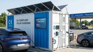
A container BESS is exactly what it sounds like: a complete battery energy storage system integrated into a standard ISO (International Organization for Standardization) shipping container. This is the essence of container BESS engineering. But the simplicity of the concept hides real engineering complexity. Inside a 20-foot or 40-foot container, you find rack-mounted battery modules, a power conversion system (PCS), a thermal management unit (HVAC or liquid cooling), a fire suppression system, and an energy management system (EMS) that controls everything.

The factory wires, tests, and commissions all of this. However, when the container arrives on site, you place it on a prepared pad, connect AC and communications cables. The system is operational — typically within a day or two.
Figure 1: Internal layout of a 20-foot container BESS showing battery racks, power conversion system, liquid cooling, and fire suppression.
This is fundamentally different from a building-integrated BESS. Consequently, the project timeline, where you pour a concrete slab, erect a structure, install racks, pull cable, and commission on site over weeks or months. A building BESS makes sense for permanent utility-scale installations where the site is stable and the timeline is flexible.
However, for remote industrial sites, emergency power, mining operations, or any deployment where speed, mobility, or relocatability matters, the container approach wins. You also get the advantage of factory-controlled quality: every connection, every thermal sensor. However, every safety interlock is tested under controlled conditions before the container leaves the factory floor.
The trade-off is that you are constrained by ISO container dimensions. However, within these constraints a 20-foot container gives you about 14.5 square meters of internal floor area. A 40-foot high-cube container roughly doubles that. This physical constraint forces discipline in component selection and layout. Which, in practice, often produces a better-integrated system than a building where space feels unlimited until the fire marshal visits.
ISO Container Types and Structural Modifications — Core Container BESS Engineering Decisions
Container Selection: Size, Type, and Certification
The container is the chassis of your BESS. Therefore, the starting point for container BESS engineering is choosing the right box. Most systems use a 20-foot ISO container (6.06 m x 2.44 m x 2.59 m) or a 40-foot container. A 10-foot container suits smaller applications like remote telecom or field command posts. High-cube (HC) variants add 30 cm of internal height, which matters when you are stacking tall battery racks or routing overhead cable trays.
CSC (Container Safety Convention, the international standard for shipping container structural safety) certification is non-negotiable. In fact, a CSC plate means the container meets the International Convention for Safe Containers and is approved for international shipping. Without it, you cannot legally ship the container by sea. For container BESS engineering applications, the CSC certification must remain valid after structural modifications — a requirement that many first-time buyers overlook. However, always ask the manufacturer whether their modified container retains its CSC plate.
| Container Type | External (LxWxH) | Internal Area | Typical Capacity | Best For |
| 10 ft | 3.0 x 2.44 x 2.59 m | ~7 m2 | 30-40 kWh | Telecom, small field office |
| 20 ft | 6.06 x 2.44 x 2.59 m | ~14.5 m2 | 200-300 kWh | Mining, hospital, microgrid |
| 20 ft HC | 6.06 x 2.44 x 2.90 m | ~14.5 m2 | 240-350 kWh | Higher rack density |
| 40 ft | 12.19 x 2.44 x 2.59 m | ~29 m2 | 450-600 kWh | Multi-building, utility |
| 40 ft HC | 12.19 x 2.44 x 2.90 m | ~29 m2 | 480-700 kWh | Large humanitarian base |
Structural Modifications: What the Container Needs for BESS Service
A standard shipping container is not ready to house batteries. Specifically, it needs modifications it needs modifications, and each modification must preserve structural integrity and CSC compliance. The most important modifications for container BESS engineering include the following.
Blast panels and pressure relief are the first priority. During a thermal runaway event, battery cells release flammable electrolyte vapor. If this gas accumulates inside a sealed container, it can create an explosive atmosphere. Blast panels — also called deflagration panels or explosion vents — are engineered weak points in the container walls or roof. However, they open at a design pressure (typically 1-2 kPa) to vent gas before it reaches explosive concentration. The NFPA 855 standard now references the need for deflagration venting. UL 9540A testing evaluates whether propagation can occur at the installation level.
Fire-rated partitions separate battery compartments from control electronics. For example, a typical layout places batteries in one zone, PCS and switchgear in another, and the EMS and communications equipment in a third. Partitions rated for 60 to 120 minutes give operators time to respond and contain any incident to a single zone. Cable penetrations through these partitions use fire-stop collars or intumescent seals that swell when heated, closing the opening automatically.
Door reinforcement and security matter for remote sites. Standard container doors with padlock hasps are not enough for equipment worth hundreds of thousands of dollars. Reinforced door frames, multi-point locking systems, and tamper switches connected to the EMS are standard practice. For foldable container systems, the hinge and latch mechanisms need particular attention because they experience repeated mechanical cycling in field conditions.
Environmental sealing goes beyond the standard IP (Ingress Protection) rating. For instance, container BESS units installed container BESS installed in desert conditions need filtered ventilation to exclude fine sand while maintaining airflow for cooling. Arctic deployments need heated door seals to prevent ice locking. Coastal installations need C5-M corrosion protection per ISO 12944 for salt spray resistance. However, the IP rating (typically IP55 or IP65 for outdoor BESS) only tells part of the story. Real-world sealing must account for the specific environmental stressors at the deployment site.
Finally, foldable container designs deserve special attention. In fact, a foldable solar container, such as our HJ-FBESS series, deploys photovoltaic panels from the container itself. The container structure must withstand not only static shipping loads but also the dynamic forces of repeated folding and unfolding cycles.
This requires reinforced hinge points, locking mechanisms that hold the deployed configuration in wind, and cable management systems that flex without fatigue. However, the advantage is dramatic: a foldable container BESS can go from shipping configuration to full power output in as little as 30 minutes. By comparison, a ground-mount PV array takes days. For disaster relief or rapid-response mining deployments, this is the difference between operational power and a construction project.

Figure 4: Foldable solar container deployment sequence — from shipping configuration (left), through unfolding (center), to full power output in approximately 30 minutes (right).
Battery Technology: Why LFP Dominates Container BESS
LFP vs. Competing Chemistries
Lithium iron phosphate (LFP, LiFePO4) has become the default chemistry for container BESS. Specifically, the reasons the reasons are well documented but worth restating because they directly affect container design. LFP cells have a nominal voltage of 3.2V, an energy density of 140-180 Wh/kg at the cell level.
A cycle life of 6,000 to 10,000 cycles at 80% depth of discharge. However, more importantly, LFP has inherently high thermal stability. The cathode does not release oxygen during decomposition, which means thermal runaway in an LFP cell is far less energetic than in NMC (nickel manganese cobalt) or NCA chemistries. This thermal stability translates directly into simpler, lighter, and less expensive fire suppression systems at the container level.
NMC (Nickel Manganese Cobalt) cells offer higher energy density — 200 to 250 Wh/kg — which is why they dominate electric vehicles where every kilogram counts. However, in container BESS engineering, weight is far less important than safety and lifetime, which shifts the balance decisively toward LFP.
In a stationary container, weight is far less important than safety and cycle life. The higher energy density of NMC comes with lower thermal runaway onset temperature (around 180 C versus 250 C for LFP) and more energetic failure modes. For a container sitting unattended at a remote mining site or disaster zone, LFP is the safer choice.
| Parameter | LFP | NMC | Sodium-Ion (Emerging) |
| Energy Density (cell) | 140-180 Wh/kg | 200-250 Wh/kg | 120-160 Wh/kg |
| Cycle Life (80% DoD) | 6,000-10,000 | 1,500-3,000 | 3,000-6,000 |
| Thermal Runaway Onset | ~250 C | ~180 C | No propagation observed |
| C-rate (continuous) | 0.5C-1C | 1C-2C | 0.5C-1C |
| Operating Temp Range | -20 to 60 C | 0 to 45 C | -40 to 60 C |
| Container Suitability | Excellent | Moderate (safety burden) | Promising (early stage) |
Cell Form Factors and the Large-Format Trend
Container BESS design starts at the cell level. For example, the industry is moving from the 280-314 Ah cell generation to large-format cells of 500 Ah and above. CATL, BYD, CALB, EVE Energy, Hithium, and REPT Battero all now offer cells in the 560-688 Ah range. Larger cells mean fewer interconnects, simpler busbar design.
However, less wiring per megawatt-hour — all of which improve reliability and reduce integration cost. However, large-format cells also concentrate more energy in a single point of failure. The thermal management system designers must plan to remove heat effectively from a physically larger thermal mass. In fact, the battery management system (BMS) needs finer-grained cell-level monitoring because one large cell failing is a larger event than one small cell failing.
Temperature is the dominant factor in LFP degradation. For example, research published in 2026 shows that LFP cells operating consistently above 50 degrees C can lose 20 to 30 percent of their cycle life. This is a central concern in container BESS engineering. Research published in 2026 shows that LFP cells operating consistently above 50 C can lose 20-30% of their capacity within the first decade.
Below 35 C, degradation is far slower — typically under 2% per year. In container BESS engineering, this is why thermal management is not a nice-to-have; it is the single biggest determinant of system life. However, a BESS container with poor cooling that lets internal temperatures climb 10 C higher than a well-designed competitor is effectively shortening its useful life by years.
Depth of Discharge and Calendar Aging
Depth of discharge (DoD) — how much of the stored energy you use before recharging — directly affects cycle count. For instance, an LFP cell cycled at 80% DoD (discharging from 90% to 10% state of charge) might deliver 7,000 cycles to 80% of original capacity. The same cell at 100% DoD might deliver 4,000 cycles.
Most container BESS sizing tools and vendor proposals assume 80% DoD as the standard operating regime, which balances usable energy against longevity. However, calendar aging. The gradual capacity loss that occurs even when the battery sits idle. Accelerates at high state of charge. Keeping cells above 90% SoC for extended periods increases calendar aging rates. A well-designed EMS will maintain cells at 50-80% SoC during standby and only charge to full before a known discharge event.
Thermal Management in Container BESS Engineering: The Factor That Determines System Life
Why Cooling Matters for Container BESS
Every watt-hour of energy that passes through a BESS generates heat. Consequently, round-trip efficiency losses — typically 5-12% depending on architecture — end up as thermal energy inside the container. Without active cooling, a sealed container in direct sunlight can reach internal temperatures above 60 C in hours. At those temperatures, LFP degradation accelerates dramatically, fire risk increases, and inverter electronics may derate or shut down. However, the thermal management system (TMS) has one job: keep every cell in the container within its optimal temperature window, typically 15-35 C for LFP, regardless of ambient conditions outside.
The cost of the TMS (Thermal Management System) is not trivial. It typically accounts for 5-8% of total system Capex and 10-15% of internal container volume. The auxiliary power it consumes — running compressors, pumps. Fans — can reach 15 MWh per year per megawatt-hour of installed BESS capacity. However, this auxiliary load is a direct hit to system efficiency and must be factored into any total cost of ownership calculation.
Air Cooling vs. Liquid Cooling
Air-cooled containers use fans and ducted airflow to carry heat away from battery racks. However, this is the simpler approach in container BESS engineering, this is the simpler approach: fewer components, lower first cost, easier maintenance.
The limitation is heat removal capacity. Air has low specific heat (about 1.0 kJ per kg per K) compared to liquid coolants. However, in hot ambient conditions — above 40 C — air cooling struggles to maintain temperature differentials. Fans run continuously at high speed, consuming significant auxiliary power. Air-cooled systems work well for smaller containers, moderate climates, and applications where simplicity is the priority.
Liquid cooling circulates a water-glycol mixture through cold plates. However, the coolant the coolant’s higher thermal capacity and the direct thermal path from cell to cold plate enable much tighter temperature control. Liquid-cooled containers can maintain cell temperatures within a 2-3 C band across the entire rack, compared to 5-8 C variation in air-cooled systems.
This uniformity extends cell life because the weakest cell — the hottest one — no longer drags down the entire string. However, for large-format cells above 300 Ah, liquid cooling is rapidly becoming the standard. For containers deployed in desert, tropical, or high-altitude-high-solar-radiation environments, liquid cooling is essentially mandatory if you want the system to deliver its rated cycle life.
| Feature | Air Cooling | Liquid Cooling |
| Temperature uniformity | +/-5-8 C | +/-2-3 C |
| Auxiliary power | Moderate (fans) | Higher (pumps + chillers) |
| Capex | Lower | 15-25% higher |
| Maintenance | Filter changes, fan replacement | Coolant checks, pump seals |
| Hot climate capability | Degrades above 40 C ambient | Effective to 50 C+ |
| Best for | Small containers, mild climate | Large format cells, extreme environments |
Container-Level Thermal Design
Thermal management does not stop at the cooling unit selection. In fact, container insulation container insulation, solar reflectivity, and internal airflow paths all matter. A standard ISO container painted dark absorbs significant solar radiation — enough to add several kilowatts of heat load in direct sun. High-reflectivity roof coatings (solar reflectance index above 100) can reduce roof heat gain by 30-40%.
However, internal airflow designers must plan so that cooled air reaches every rack uniformly. Dead zones behind equipment or in corners create hot spots that degrade cells unevenly. For foldable container systems, the thermal design must account for the deployed configuration when PV panels shade portions of the container and change the external heat load profile. In fact, these are the details that separate a system that meets spec on paper from one that performs in the field.
Power Conversion and System Architecture
DC-Coupled vs. AC-Coupled: The Fundamental Choice
In container BESS engineering, the DC-coupled architecture connects the photovoltaic array to the battery through a shared DC bus and a single power conversion stage. Therefore, round-trip efficiency can reach 88 to 95 percent. Solar power flows from the PV modules through DC-DC converters into the battery.
From the battery through the PCS inverter to the AC load. The round-trip efficiency is 88-95% because you avoid the double conversion penalty of AC coupling (DC-AC-DC-AC). However, this architecture is particularly well suited to container BESS engineering because it reduces component count inside the space-constrained container and eliminates a separate PV inverter. Every component you do not install is a failure point you do not manage.
Figure 2: DC-coupled architecture (left) achieves higher round-trip efficiency with a single power conversion stage, compared to AC-coupled architecture (right) with separate PV and battery inverters.
In an AC-coupled system, the PV array has its own dedicated inverter that outputs AC power. In contrast, the battery has the battery has a separate bidirectional inverter. This doubles the power electronics and introduces an extra conversion step: PV DC to PV Inverter AC to Battery Inverter DC to Battery. The extra conversions cost 3-5% in round-trip efficiency. However, AC coupling makes sense when you are adding storage to an existing solar installation, or when the PV array and battery are physically far apart. For a new, factory-integrated container system, DC coupling is usually the better choice.
DC coupling also enables a feature called overloading. Specifically, you can connect more PV capacity to the DC bus than the inverter’s AC rating, because surplus DC power charges the battery directly without passing through the inverter. For example, a container with a 100 kW PCS can support 120-150 kWp of PV if the DC-DC converters and battery charge acceptance are sized for it. This lets you capture more solar energy during peak hours without upsizing the inverter, improving system economics.
PCS, EMS, and BMS: The Three-Layer Control Stack
The power conversion system (PCS) is the bidirectional inverter that moves power between the DC battery bus and the AC load. For example, modern container BESS engineering PCS units operate at 98-99% peak efficiency and support grid-forming mode. Meaning they can create a stable AC voltage reference without a grid connection. This capability is essential for off-grid and microgrid applications where the container is the sole power source.
The battery management system (BMS) monitors every cell: voltage, temperature, state of charge (SoC), and state of health (SoH). Consequently, it balances cells voltage, temperature, state of charge (SoC), and state of health (SoH). It balances cells to prevent overcharge or overdischarge of any single cell and can isolate a faulty module before it affects the rest of the container BESS engineering approach.
The energy management system (EMS) sits above the BMS and PCS, making decisions about when to charge, when to discharge. How to optimize for tariff structures, generator fuel savings, or grid stability requirements. However, for remote containers, the EMS typically includes satellite or cellular connectivity for remote monitoring and over-the-air updates. HighJoule systems, for example, transmit real-time operating data, fault alerts. GPS location via 4G or satellite link. A feature that matters when your container is in the Gobi Desert or on a mountain plateau with no local technical staff.
Safety and Compliance: From Lab Tests to Container Design
Safety Certification: The Multi-Standard Landscape for Container BESS
Safety certification for container BESS engineering spans multiple jurisdictions, and the requirements depend on where your project is located. For the North American market, UL 9540A (ANSI/CAN/UL 9540A:2019) is the key standard. It evaluates thermal runaway fire propagation in battery energy storage systems.
It tests at four progressively larger scales. At Level 1, a single cell is driven into thermal runaway to measure gas composition, temperature, and propagation. The next stage, Level 2, expands to a full module. Level 3 tests a complete rack or unit, while Level 4 evaluates the full installation — multiple containers — for fire spread between units.
Figure 3: UL 9540A test progression — from single cell (Level 1) through full installation (Level 4), each level evaluates thermal runaway propagation at increasing scale.
For the Chinese and many international markets, equivalent safety frameworks apply. China GB/T 36276 (China national standard for lithium-ion battery safety in power storage) governs lithium-ion battery safety for power storage, and GB/T 34131 covers BMS technical requirements.
The international standard IEC 62933-5-2 addresses fire safety for electrochemical energy storage systems specifically. Most manufacturers publish UL 9540A test data at the cell and module levels. However, far fewer publicly share unit-level or installation-level results. When evaluating a container BESS vendor, ask for Level 3 and Level 4 test reports — or at minimum, a detailed description of the containment strategy demonstrated at those levels.
NFPA 855: Installation Requirements for the US Market
For installations in the United States, NFPA 855 (Standard for the Installation of Stationary Energy Storage Systems) sets physical installation requirements. For example, key provisions for container BESS include the following. Maximum stored energy per container: NFPA 855 limits individual BESS units to 600 kWh in aggregate unless additional fire protection measures are in place.
Separation distance: a minimum of 3 feet between container BESS units unless fire-rated barriers are installed. Access and egress: clear pathways for emergency responders and fire department access. For projects outside the US, local fire codes and IEC-based standards typically apply. Our engineering team designs each container to the jurisdiction-specific requirements of the destination country.
For international buyers, equivalent standards include IEC 62933 (International Electrotechnical Commission standard for electrical energy storage systems), the EU Battery Regulation (2023/1542, effective 2024-2027 with phased requirements), and China GB/T 36276 for lithium-ion batteries for power storage. A container BESS sold into multiple markets should carry certification documentation for each target jurisdiction. The important question to ask a vendor is not just “which standards do you meet” but “can you provide compliance documentation for the specific country where our project is located.”
Fire Suppression System Types
Three fire suppression technologies are common in container BESS engineering. Aerosol suppression uses a potassium-based compound that, when activated, produces a fine particulate cloud that chemically interrupts the combustion chain reaction. It requires no pressurized cylinders, has a long shelf life, and is effective for enclosed spaces like containers.
Gas suppression — typically NOVEC 1230 or FM-200 — floods the container with an inert gas that displaces oxygen below combustion threshold. However, it is clean (no residue) but requires pressurized storage and may need refilling after discharge. Water mist systems use high-pressure nozzles to create a fine water fog that cools surfaces and displaces oxygen. They are effective for fire suppression and cooling but introduce water into an electrical environment, requiring careful design of drainage and electrical isolation.
The most important consideration is integration with the BMS. Specifically, the suppression system should trigger automatically on BMS fault signals. Cell temperature exceeding threshold, voltage anomalies indicating internal short circuit, or gas detection sensors registering off-gas signatures. Manual pull-stations at container access points provide a redundant trigger path for on-site personnel. The system should also include a “do not re-energize” lockout that prevents the BMS from reconnecting battery contactors after a suppression event until the cause has been investigated.
Application Profiles: Matching Engineering to Mission
Mining and Heavy Industry
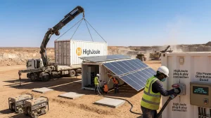
Mining sites present the harshest conditions for container BESS engineering: fine conductive dust, 24/7 vibration from heavy equipment, ambient temperatures that swing from below freezing at night to above 45 C during the day, and often altitude above 3,000 meters where air density reduction derates cooling fans and compromises air-cooled designs.
For mining, liquid cooling is the right choice. The container needs enhanced air filtration — G4 or better pre-filters with M5 main filters. It also needs reinforced mounting points for battery racks to survive constant vibration and sealed cable entries to prevent dust ingress. Your container BESS engineering specification for mining should also require altitude-rated PCS units — standard inverters derate above 2,000 meters. However, altitude-rated units maintain full power to 4,000 meters or higher.

Figure 5: Container BESS deployed at a remote mining site. Liquid-cooled architecture handles extreme ambient temperatures, conductive dust, and 24/7 vibration.
Disaster Relief and Emergency Response
Speed is everything in disaster response. Therefore, container BESS engineering prioritizes this from the start. A container that deploys in 30 minutes. Unfold the PV arrays, connect one cable, press start. Transforms what aid organizations can deliver. Foldable container BESS designs excel here because the PV generation is integrated: no separate solar field to survey, grade, and mount.
The container itself is the power plant. However, for emergency applications, the container should include pre-installed distribution panels with standard connector types (CEE-form industrial sockets, camlock connections) so that field hospitals, water purification units, and communications gear can plug in immediately. Dual-fuel capability — the ability to accept generator input as backup or supplement — is also critical. Solar-only systems in disaster zones with unpredictable weather need a fallback.
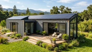
Remote Community and Island Microgrids
In container BESS engineering for off-grid communities in remote locations, the requirements shift significantly. Whether a village in sub-Saharan Africa, an island in Southeast Asia, or a research station in the Arctic. Need reliable power with minimal maintenance. The container BESS approach works well here because the system is pre-integrated and tested before shipment.
For community microgrids, the EMS takes on added importance: it must manage multiple load priorities (clinic first, school second, residential third), integrate with whatever existing diesel generators the community already owns, and present a simple operator interface that a trained local technician can use. Remote monitoring over satellite link becomes essential because sending a technician to site may involve a multi-day journey.
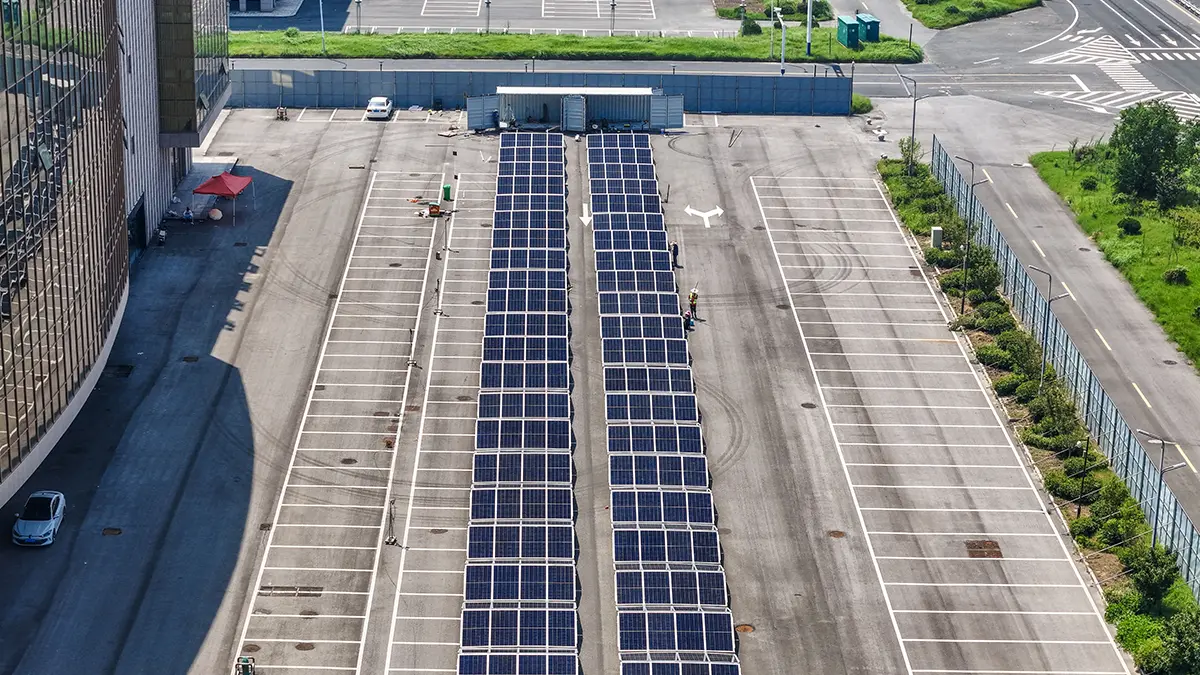
Commercial and Industrial (C&I) Peak Shaving
For commercial and industrial applications connected to a utility grid, container BESS engineering serves a different purpose: reducing demand charges by discharging during peak tariff periods. The engineering priorities shift. Instead of extreme-environment ruggedness, the focus moves to round-trip efficiency (every percentage point lost is revenue lost), grid code compliance (the system must meet the local utility’s interconnection requirements), and scalability (multiple containers may be paralleled as the facility grows). Liquid cooling still matters for efficiency. However, the thermal challenge is continuous cycling. Charging during midday solar production, discharging during evening peak pricing. Not survival in extreme ambient conditions.
Our Deployments: Container BESS Engineering in the Field
Romania: 1.075 MWh Integrated PV-Storage
For example, a 1.075 MWh container BESS system deployed in Romania demonstrates the turnkey advantage of container BESS engineering done right. Four container units, each with 46 kWp of foldable PV and 241 kWh of LFP storage, were delivered about 40 days from contract.
The DC-coupled architecture with liquid cooling maintains cell temperatures within a 3 C band across all four containers despite summer ambient temperatures exceeding 35 C. The EMS monitors and balances across the four containers, treating them as a single virtual power plant while maintaining independent safety systems in each container. However, the system operates year-round, serving a commercial facility with both solar self-consumption and peak shaving functions.
United States: Modular Pod Deployment
Similarly, our modular 8 kW / 20 kWh pod configuration deployed in the USA shows how container BESS engineering scales down for smaller applications without sacrificing the container concept. Using N-Type TOPCon (Tunnel Oxide Passivated Contact) PV modules with 23.2% module efficiency and IP54/IP66 environmental protection, the pod-sized unit delivers the same architecture. DC coupling, integrated BMS, remote monitoring. As the full-scale 20-foot and 40-foot containers. This modular approach lets buyers start with a smaller system and add capacity in pod increments as loads grow, using the same control platform and maintenance procedures across all units.
Decision Framework: How to Evaluate a Container BESS Vendor
Specifically, use the following checklist to evaluate proposals and compare vendors on an equivalent basis. Every question maps to an engineering decision discussed above.
Container: Is the container ISO/CSC certified? Additionally, does it retain certification after BESS modifications? What corrosion protection rating (C1-C5 per ISO 12944) is applied?
Battery: What cell manufacturer, model, and capacity (Ah)? Additionally, what is the warranted cycle count, at what DoD, to what end-of-life capacity? Has the cell passed UN38.3 transportation testing?
Thermal: Liquid-cooled or air-cooled? Additionally, what is the maximum ambient temperature at which the system maintains rated power without derating? What is the auxiliary power consumption of the TMS at 35 C ambient?
Safety: UL 9540A tested at which level (cell, module, unit, installation)? Additionally, NFPA 855 compliant? What fire suppression technology is installed, and is it integrated with the BMS for automatic trigger?
Architecture: DC-coupled or AC-coupled? Additionally, what is the round-trip efficiency at rated power? Can the PCS operate in grid-forming mode for off-grid applications?
Deployment: What is the deployment time from container arrival to full power output? Additionally, what site preparation you need (pad specifications, cable trenching, clearance distances)? What lifting and transport equipment is needed?
Service: What is the warranty period on the container, battery, and power electronics? Additionally, what remote monitoring capability is included? What is the guaranteed response time for on-site service?
However, the price of container BESS engineering varies widely. From about $250/kWh for basic air-cooled systems to $450/kWh or more for liquid-cooled, UL 9540A unit-level tested, foldable-container designs with integrated PV. The per-kWh number alone does not tell you much. Two 241 kWh containers at the same price per kilowatt-hour can have very different cycle lives, cooling capability, and deployment speed. Use the checklist above to normalize proposals to equivalent technical specifications before comparing prices.
Frequently Asked Questions
What is the difference between a BESS container and a building-based BESS?
A BESS container is a factory-integrated system inside a standard ISO shipping container. It ships complete, commissions in days, and you can relocate it. A building-based BESS requires on-site construction, takes weeks to months to complete, and is a permanent structure. Containers suit remote sites, temporary power, and projects where speed matters. However, buildings suit permanent utility-scale installations with no mobility requirement.
How long does a container BESS last?
An LFP-based container BESS manufacturers typically design for 15-25 years of service. The battery modules themselves you may replace them once during that period. Usually after 10-12 years when capacity has degraded to 70-80% of original. The container structure, PCS, and thermal management equipment designs target for the full service life with regular maintenance.
Can a BESS container operate in extreme cold?
Yes, with proper engineering. LFP cells can discharge at temperatures as low as -20 C, but charging below 0 C causes lithium plating and permanent damage. A cold-climate container BESS includes battery heaters (resistive pads or liquid heating loops) that warm cells to above 0 C before charging begins. The container insulation and the thermal mass of the batteries themselves help maintain temperature once warmed. However, for truly extreme cold (-40 C), additional insulation, door seal heaters, and cold-rated electronics are required.
What certifications should a container BESS have?
Minimum: UN38.3 (UN standard for lithium battery transport safety), UL 9540A (thermal runaway testing), and compliance with NFPA 855 (installation standard). For international deployment: IEC 62933, EU Battery Regulation compliance, and destination-country grid code certification. For the container itself: CSC safety approval plate. Ask for certificate numbers — not just claims of compliance.
What is a foldable solar container and when does it make sense?
A foldable solar container integrates photovoltaic panels into the container structure itself, deploying them on-site without a separate ground-mount array. The panels fold out from the container in a pre-engineered sequence, typically reaching full deployment in 30 minutes to 2 hours. This design makes sense for disaster relief, remote mining. Any application where site preparation is difficult, time is critical, or the system may need to relocate. However, the trade-off is slightly higher upfront cost compared to separate container plus ground-mount PV.
How do I size a container BESS for my application?
Start with your daily energy consumption in kilowatt-hours. Add a 20% margin for system losses and growth. Choose a DoD — typically 80% for LFP. Divide your adjusted daily consumption by the DoD to get the required battery capacity. For example, 100 kWh/day at 80% DoD means you need at least 125 kWh of installed capacity. Also verify that the PV array can recharge the battery within your available solar window. Most vendors provide sizing tools or will run these calculations as part of their proposal.
What maintenance does a container BESS require?
Quarterly: visual inspection of container seals, door gaskets, and cable entries; filter cleaning or replacement; EMS data review for trending. Semi-annually: torque check on electrical connections. Thermal imaging of busbars and terminations. Coolant level and quality check (liquid-cooled systems). However, fire suppression system inspection. Annually: full system capacity test; BMS firmware update; PCS efficiency verification; structural inspection of container and lifting points. Remote monitoring handles daily status checks and alerts for anomalies.
Can I add more containers later?
Yes — this is one of the main advantages of container BESS. Multiple containers you can parallel them on the AC side and managed as a single virtual power plant by the EMS. You do need to plan for the electrical infrastructure (switchgear, transformer capacity) to accommodate future expansion. Most EMS platforms support adding containers without major reconfiguration. However, for HighJoule systems, the HJ-FBESS series uses a modular EMS that can scale from a single container to a multi-container microgrid with minimal reprogramming.
About the Engineering Team
This guide was written by the engineering team at Shanghai HighJoule Energy Technologies Ltd., the manufacturer of the HJ-FBESS series of foldable solar container systems. We have deployed container BESS across four continents — from the Tibetan Plateau at 4,500 meters to desert mining operations in Xinjiang, from European commercial facilities to modular emergency pods in the United States.
Our certifications span multiple jurisdictions: UL 9540A and UN38.3 for North American and international transport, China GB/T 36276 and GB/T 34131 for domestic compliance, CE marking for the European market, CSC safety approval for ISO containers, and ISO 9001 for quality management. Our engineering team includes specialists in power electronics, battery chemistry, thermal systems, and international logistics — the full stack of container BESS engineering disciplines. We are headquartered in Shanghai with support offices in Europe and Southeast Asia.
Disclaimer
The information in this guide is provided for general educational purposes. Specifications, certification requirements. Standards referenced herein — including UL 9540A, NFPA 855, IEC 62933, GB/T 36276, GB/T 34131, EU Battery Regulation 2023/1542 — are subject to revision by their respective issuing bodies. However, always verify current versions with the relevant standards organization. Cost ranges cited are indicative and based on 2025-2026 market data; actual pricing depends on project-specific configuration, volume, and delivery terms.
Deployment case studies describe actual HighJoule projects, with some client details anonymized. In fact, for a specification-grade proposal for your specific project, contact our engineering team directly. All cost figures reflect 2026 market conditions and exclude inflation, taxation, and fuel-price escalation. Financial projections in this article use simple (static) payback period; formal technical proposals include dynamic payback modeling with inflation and tax assumptions. HighJoule standard warranty terms: PV modules 25 years linear output warranty, batteries 10 years or specified cycle count (whichever comes first) at 80 percent end-of-life capacity, power electronics 5 years. Extended warranty and SLA options are available by agreement.
——END——