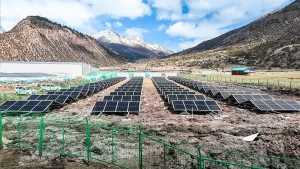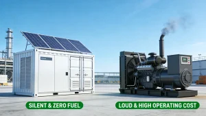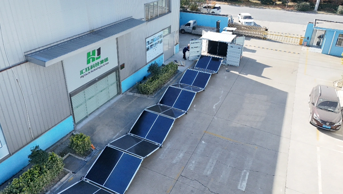
A solar container for telecom base stations combines photovoltaic (PV) generation, battery storage and power controls to reduce diesel dependence at remote sites. Solar supplies the load when available, and the battery covers periods when generation is insufficient. Whether a generator is needed regularly or only as emergency backup depends on the site’s load, seasonal solar resource and required reliability.
The HJ Solar Container product page lists two reference configurations: 3.6 kWp of PV with 30 kWh of storage, and 7.2 kWp with 50 kWh. These are starting points for a sizing review, not guarantees of continuous solar-only operation.
How a solar container powers an off-grid base station
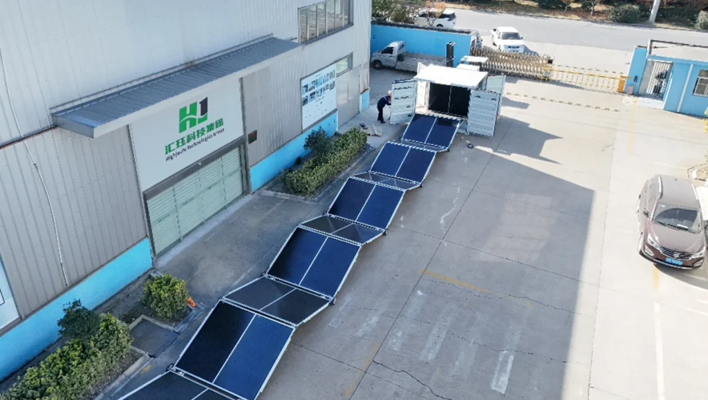
Photovoltaic modules convert sunlight into electricity, as explained in the U.S. Department of Energy’s guide to solar PV cells. In a solar-storage system, power electronics regulate generation, battery charging and delivery to the load. When PV output exceeds site demand, the surplus can charge the battery. When output falls short, stored energy supplies the difference.
Start by confirming whether the site needs DC power, AC power or both. A DC-coupled arrangement can supply compatible DC loads through appropriately specified controllers and DC/DC converters. It does not automatically require an AC microgrid. Output voltage, current capacity, protection and compatibility with existing telecom equipment must be checked.
If the battery system must supply AC loads while both the grid and generator are unavailable, the inverter must establish a stable voltage and frequency. The DOE’s explanation of inverters and grid services distinguishes grid-forming operation from grid-following operation. Specify and test standalone operation, load-step response and restart after shutdown rather than assuming that any grid-connected inverter can perform these functions.
Where diesel backup is included, set its start threshold above the battery’s minimum operating state of charge (SOC). The generator and charging equipment must support the intended combination of site load and battery recharge. A backup connector alone does not establish automatic start, safe changeover or fault recovery.
Match the container to the site load
Sizing starts with the load, not the panels. Record daily energy consumption, the hourly load profile and peak demand. Include cooling, transmission equipment, monitoring and other auxiliary loads; measuring the radio equipment alone can understate the energy requirement.
A worked example: a site averaging 1.5 kW
Assume the complete site averages 1.5 kW over 24 hours and reaches a 2.5 kW peak. Its daily energy demand is:
Daily energy demand = 1.5 kW × 24 h = 36 kWh.
At five peak sun hours per day on the intended array plane, a 7.2 kWp array gives a simple nameplate-based estimate of 36 kWh before losses. Peak sun hours describe equivalent solar energy, not the number of daylight hours. Temperature, soiling, shading, wiring and power conversion reduce the energy available to the site; energy routed through the battery incurs storage losses as well.
For this example only, assume a combined net-energy factor of 0.80 to represent those losses, including the share of energy routed through storage. This is an illustrative assumption, not a measured HJ-SG efficiency or a universal design value.
Estimated net daily energy = 7.2 kWp × 5 h × 0.80 = 28.8 kWh.
That leaves an estimated 7.2 kWh daily deficit against the 36 kWh load. Under these assumptions, the site needs more PV, another energy source or lower consumption. A larger battery can delay depletion, but it cannot correct a persistent generation deficit.
Using the same assumptions, balancing 36 kWh of daily demand would require approximately 36 ÷ (5 × 0.80) = 9 kWp. This is an energy-balance estimate, not a final array size: it provides no additional margin for prolonged poor weather or rapid battery recovery. It also exceeds the 7.2 kWp reference configuration, so expansion would require a separate engineering review.
Before selecting equipment, model the load and solar production hour by hour through the low-sun season. The European Commission Joint Research Centre’s PVGIS manual explains this approach for off-grid PV systems, including battery charge limits and unmet demand. Use a telecom load profile rather than a default household profile, and assess generator dispatch separately where applicable.
Published HJ-SG configurations
| Model | PV capacity | Storage capacity | Container size | Published DC maximum |
|---|---|---|---|---|
| HJ-SG-10 | 3.6 kWp | 30 kWh | 10 ft | 24 kW |
| HJ-SG-20 | 7.2 kWp | 50 kWh | 20 ft | 36 kW |
Source: the specification table on the HJ Solar Container product page. The page also describes battery storage and intelligent management as optional configurations; confirm the equipment included in the quotation.
The published DC maximum is not the PV output or a guaranteed continuous battery-discharge rating. Confirm the rating’s definition, operating voltage and duration, together with the selected battery, converter and protection limits. The final equipment schedule should also state the generator interface and any expansion provisions.
Choose battery storage for usable autonomy
Battery capacity in kilowatt-hours describes stored energy, while power in kilowatts describes the rate of delivery. For a telecom site, the useful question is how much energy can reach the load before the battery reaches its reserve limit.
Estimated autonomy = nominal battery capacity × available SOC window × discharge-path efficiency ÷ average site load.
For illustration, assume an available SOC window of 80 percentage points, such as starting at 95% and stopping at a 15% reserve. Also assume 95% efficiency from the battery to the load, a steady 1.5 kW total load and no solar contribution. These assumptions give:
| Nominal capacity | Energy delivered to the load | Estimated runtime |
|---|---|---|
| 30 kWh | 30 × 0.80 × 0.95 = 22.8 kWh | 15.2 hours |
| 50 kWh | 50 × 0.80 × 0.95 = 38.0 kWh | 25.3 hours |
These estimates assume the battery still provides its stated nominal capacity at the operating temperature. They do not include an additional allowance for ageing or temperature-related capacity reduction. Starting at a lower SOC, increasing the load or holding a larger reserve shortens runtime.
Under these assumptions, a 30 kWh battery could cover a 12-hour, 18 kWh overnight load. A 50 kWh battery extends the interval, but it does not provide several consecutive sunless days at 1.5 kW. Confirm both the required autonomy and how quickly the system can recharge afterward.
For a lithium iron phosphate (LiFePO4) battery option, request the usable capacity, charge and discharge limits, operating-temperature range and warranty conditions. A cycle-life figure should identify its test conditions and retained-capacity threshold, not stand alone as a service-life promise.
A telecom project example
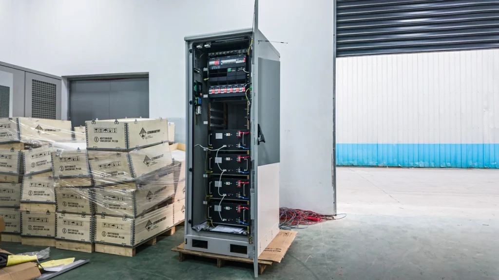
HighJoule’s Kenya telecom solar-storage project describes a cabinet-based off-grid installation with solar-priority operation, battery support, remote monitoring and optional emergency diesel backup.
The case illustrates the operating approach, not a confirmed HJ-SG container deployment or a battery-sizing benchmark. Its cabinet arrangement should not be treated as interchangeable with the container configurations above.
When a solar container fits, and when it does not
A solar container is worth evaluating where the grid is unavailable or unreliable and fuel deliveries create a recurring operational burden. GSMA’s work on renewable energy for mobile towers identifies diesel dependence at remote off-grid and weak-grid sites as an industry challenge.
Containerized delivery can simplify equipment packaging and transport, but it does not eliminate site work. Check foundations, lifting access, PV mounting space, shading, cabling, earthing, thermal management and commissioning requirements before choosing the enclosure format.
Where reliable grid power and suitable equipment already exist, compare a container with a smaller outdoor cabinet or a retrofit of the existing power system. Where the required PV capacity or autonomy exceeds the published configurations, evaluate an engineered expansion or a different system size. Do not assume that extra PV strings or battery cabinets can be connected without checking electrical and control compatibility.
Selection checklist
| Selection question | What to confirm |
|---|---|
| Site load | Daily consumption, hourly profile, peak demand and auxiliary loads, with an allowance for planned expansion. |
| Electrical interface | DC voltage range and current requirements; AC voltage, frequency and standalone operation where needed. |
| Solar resource | Location, seasonal irradiation, shading, panel orientation and available installation area. |
| Battery autonomy | Required hours without solar, usable SOC window, temperature effects and capacity at the intended service age. |
| Power capability | Continuous and peak ratings of the battery and conversion equipment, including operating-temperature limits. |
| Backup and recovery | Generator start and stop settings, simultaneous load and charging demand, restart sequence and failed-start alarms. |
| Remote monitoring | SOC, battery temperature, source power, generator runtime and alarms, with a defined response process. |
| Installation and acceptance | Site access, thermal design, protection drawings and tests covering loss of supply and restoration. |
Frequently asked questions
Can a solar container power a telecom base station without diesel?
Potentially, but only when PV capacity, usable storage and site conditions support the required reliability. A design that balances energy on an average sunny day may still run short during a prolonged low-sun period. Verify the seasonal energy balance and battery recovery before removing a backup source.
Does an off-grid telecom solar system need battery storage?
For solar-led operation through the night, the site needs stored energy or another dispatchable power source. Battery storage allows the site to operate between solar charging periods without keeping a generator running continuously. The required capacity depends on the load and the intended interval without charging.
How long can a 50 kWh battery run a telecom base station?
At a steady 1.5 kW load, an 80-percentage-point available SOC window and 95% battery-to-load efficiency, the illustrative runtime is about 25.3 hours without solar. Actual runtime depends on starting SOC, battery condition, temperature and total site demand.
What information is needed for a quote?
Provide the site location, daily consumption, load profile, peak demand, required DC or AC output, autonomy target and existing grid or generator arrangement. Include available PV space and operating temperatures so the proposal addresses installation constraints as well as energy capacity.
Request a site-specific sizing review
Send these operating details for a telecom solar-container sizing review. The proposal should define expected solar contribution, usable battery autonomy, backup operation and the equipment included. Explore the solar container product range to compare the available system formats.
Last Updated on 09/18/2026