A nominal 48 V label identifies a voltage family. To approve equipment for a telecom site, a buyer still needs the permitted input window, the polarity reference, the return arrangement and the expected voltage at the actual equipment terminals. Those details become important when the battery discharges, the rectifier raises charging voltage or a long feeder carries a higher current.
The first drawing should show the conversion equipment, the common DC bus and the individual protected feeders. Put the battery connection on that drawing as well. This allows every voltage and current requirement to be attached to a physical point.
What produces the DC supply?
The rectifier converts an accepted AC source into controlled DC output. That output can feed the radio load and support charging through the approved battery interface. The battery can in turn support the same DC system while the AC conversion path is unavailable.
For a fuller equipment explanation, the question what is a rectifier in telecom? is addressed in Huijue Group’s system guide. The guide connects the conversion module with the shelf, controller and distribution, helping a project team trace the supply from the source to the radio.
Polarity deserves its own line in the interface schedule. In a system using a nominal negative 48 V convention, the negative conductor is below the designated return reference. The project must identify how the DC return relates to the bonding arrangement. A technician needs that information before comparing readings taken to different reference points.
The load sees the voltage at the end of its circuit
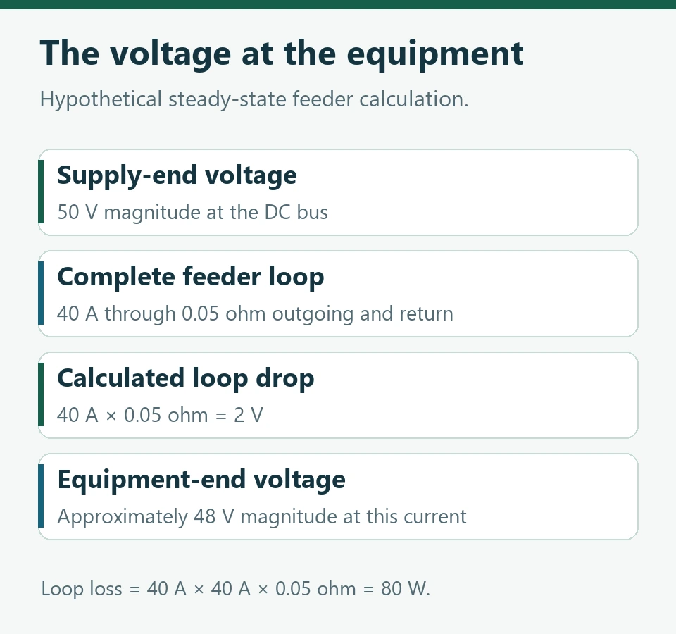
Suppose a hypothetical feeder supplies 40 A through a combined outgoing-and-return resistance of 0.05 ohm. The calculated loop drop is 2 V, and the cable loss at that current is 80 W. If the supply-end magnitude is 50 V, the load-end magnitude is approximately 48 V under those simplified conditions.
At a different load current, the drop changes. At a different conductor temperature, the resistance changes. The example provides a way to test whether a voltage budget is plausible. Cable selection must also include ampacity, installation conditions, protection and the connected equipment’s requirements.
Read interface requirements at the correct boundary
ETSI EN 300 132-2 V2.8.1 defines the nominal negative 48 V interface at the consuming ICT equipment and includes a normal service voltage range from −40.5 V to −57.0 V. Apply that reference only where the equipment and project declare the interface. The standard’s measurement location matters because intervening distribution can produce a drop. ETSI EN 300 132-2
The offered radio, battery, rectifier and any DC/DC converter each have their own permitted operating conditions. Collect those declared windows and show how the intended normal and recovery states fit together. Raising a bus setpoint can affect several connected loads and the battery simultaneously.
Use an interface row that another engineer can check
For each load branch, record the equipment model, polarity, measurement point, approved voltage limits, continuous and transient current, feeder route and return conductor. Add the source settings and the maximum expected loop drop for the relevant operating condition.
A useful review asks whether the load will remain within its declared limits at both ends of the operating envelope. Low battery voltage and high feeder current can govern one end. Battery charging and a lightly loaded feeder can govern the other. The site drawing should explain both.
A quotation described as a complete 48 V system should therefore include an interface schedule as well as a bill of materials. This gives the buyer a way to compare equipment from different supply packages and gives commissioning personnel a defined location for each acceptance measurement.
Huijue Group works on telecom energy equipment and integration. This article presents general engineering guidance and explicitly labelled planning examples.
Last Updated on 11/18/2026