A solar container site is ready only when the selected unit can reach the site, be lifted into position, unfold and stow without obstruction, sit on a verified load-bearing and drained support, and connect safely to the load. A concrete slab is not the universal default: the right base depends on the unit’s operating mass and support points, soil conditions, frost and flood exposure, wind design, installation duration, and local approval requirements.
This guide explains the site information a supplier, civil engineer, electrical designer, and lifting contractor need before delivery. If you are still defining the system concept, start with the distinction between a standard container with solar equipment and a purpose-built solar-powered shipping container. Then assess the whole operating site—not merely a rectangle equal to the container’s transport dimensions.
Start With the Whole Operating Envelope, Not the Container Length
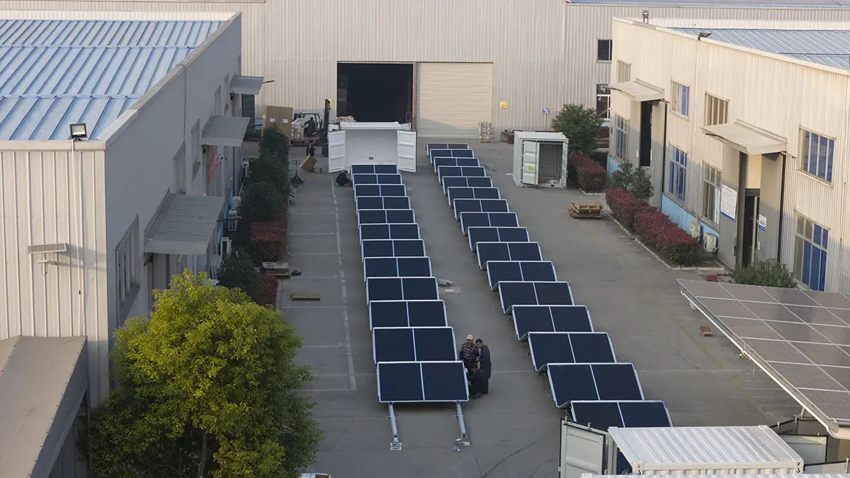
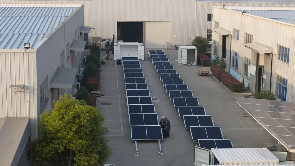
Transport dimensions answer only one question: what arrives on the vehicle? They do not show how much land is needed to unload, deploy, maintain, reconnect, or stow the system. A useful early survey separates the site into five connected zones:
- Transport corridor: the route from the public road or site entrance to the final position, including gates, bends, overhead restrictions, gradients, bridge limits, and ground that must carry the delivery vehicle.
- Offloading zone: the working area for the crane, side-loader, or other approved handling method, including equipment setup, outrigger support, rigging clearance, and an exclusion zone.
- Support footprint: the verified bearing points and prepared ground beneath the container and any deployed supports.
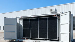
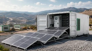
- Deployment envelope: the full area swept or occupied while the array unfolds, operates, and returns to its transport position.
- Operating envelope: the remaining clearance for maintenance, ventilation, electrical equipment, cable routes, vegetation control, and emergency access.
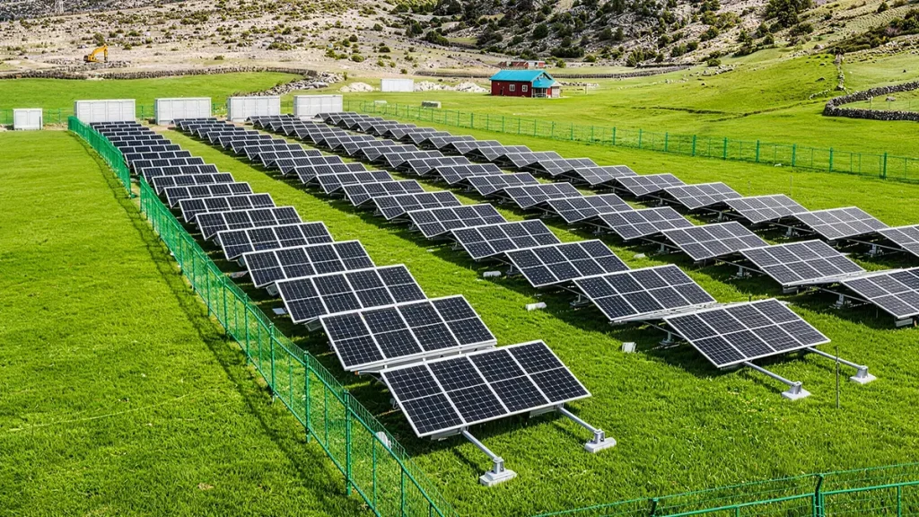
Obtain the manufacturer’s current general arrangement drawing for the exact configuration. It should identify transport mass, operating mass, center of gravity, approved lifting points, structural support points, deployed geometry, access doors, ventilation openings, and connection locations. Do not infer these values from the nominal container size or from a photograph of another project.
Verify the Ground Before Choosing a Foundation
“No foundation needed” is not a safe universal rule. A container frame can transfer loads through concentrated points, while folding structures may introduce additional reactions in the deployed condition. Whether the support is compacted aggregate, precast elements, piers, screw piles, a slab, or another engineered solution depends on the equipment loads and the site.
At minimum, record soil type, evidence of fill or previous excavation, surface slope, soft areas, seasonal groundwater, frost depth where relevant, flood level, erosion, and buried services. A geotechnical or civil professional should determine allowable bearing, settlement risk, drainage treatment, and the required support design for long-term or critical installations. Wind, snow, seismic, and other environmental loads must be assessed under the locally adopted codes.
| Site condition | Why it matters | Likely next check |
|---|---|---|
| Known competent, level ground | May allow a relatively simple prepared support, but concentrated reactions still need verification. | Compare site bearing and settlement criteria with manufacturer loads and support points. |
| Uncontrolled fill, soft soil, or visible settlement | Level can be lost and doors, frames, or deployment mechanisms can distort. | Geotechnical investigation and a designed foundation or ground-improvement method. |
| Flood-prone or poorly drained land | Water can erode support, restrict access, and expose electrical equipment to unacceptable conditions. | Confirm design flood level, equipment elevation, drainage outfall, and access during severe weather. |
| Temporary installation | Short duration does not remove structural, electrical, wind, or environmental obligations. | Use a reversible solution only after the same load and stability checks are completed. |
Keep the support level and within the equipment supplier’s stated tolerances. Those tolerances are product-specific and should appear on the approved installation drawing—not be copied from a generic article.
Design Drainage Around the Container and Deployed Array
Drainage is more than keeping the container floor dry. Runoff from access roads, compacted pads, roofs, and panel surfaces can concentrate at the edge of the installation. Ponding can soften subgrade; fast flow can scour support zones; sediment can block channels; and unmanaged water can make maintenance access unsafe.
Grade the prepared area so water moves away from structural bearing points and electrical equipment toward an approved discharge path. Keep swales and drains outside areas needed for lifting, deployment, and vehicle turning. Where rows of panels create drip lines, protect vulnerable soil from erosion and establish vegetation or other suitable cover around—but not inside—the equipment clearance zone.
For larger sites, document pre-development and post-development runoff assumptions. The National Laboratory of the Rockies’ PV-SMaRT stormwater work highlights soil compaction, soil depth, ground cover, and hydraulic disconnection as relevant factors in photovoltaic runoff behavior. The principle is widely useful, but the actual drainage design must follow local rainfall data, environmental requirements, and permitting rules.
Check Solar Access Without Blocking Deployment or Maintenance
A clear patch of ground is not automatically a productive solar location. Model solar resource and shading for the proposed array position and operating geometry. Nearby trees, buildings, stockpiles, fences, terrain, or future construction may cast longer shadows during low-sun months than they do during a summer site visit.
Tools such as the Global Solar Atlas, the European Commission’s PVGIS, and NREL PVWatts can support early energy estimates. They do not replace an accurate horizon survey, the equipment’s verified array geometry, or a project energy model.
Preserve clear space for stowing as well as unfolding. Establish a vegetation-management plan that avoids shading, fire exposure, blocked drains, and damage to cables or moving parts. Locate new fences and barriers outside the swept path and required service access.
Plan Delivery and the Lift Before the Unit Ships
Survey the route with the actual delivery configuration in mind. Check gate width and height, turning radii, overhead lines, branches, gradients, crossfall, bridge ratings, underground structures, road edges, and the load capacity of wet-season access. The final approach should allow the vehicle and lifting equipment to enter, work, and exit without crossing an unsupported foundation, buried cable route, drain, or deployed array area.
A competent lifting contractor should prepare the lift plan using the supplier’s confirmed mass, center of gravity, lifting points, rigging requirements, and site conditions. The International Convention for Safe Containers addresses container approval and safe transport-related handling; it is not a substitute for a site-specific foundation or lift design. In the United States, container handling also falls within applicable requirements such as OSHA 29 CFR 1917.71 in marine-terminal operations.
Agree who supplies the crane or side-loader, rigging, mats, traffic control, spotters, and exclusion barriers. Confirm the weather limits and the contingency if the prepared position or access route is unacceptable on delivery day. For a broader sequence of pre-delivery, arrival, deployment, and commissioning activities, use the solar container deployment timeline.
Reserve Space for Cables, Earthing, Service, and Emergency Access
Fixing the container location before routing the electrical connection often creates avoidable bends, long cable runs, trip hazards, or conflicts with drainage. Map the load connection, switchgear, earthing and bonding system, communications, auxiliary supply, and any trench or protected above-ground route before civil work begins. Keep cable routes away from moving structures, lifting setup areas, vehicle paths, sharp edges, standing water, and locations where future excavation is likely.
PV array design, wiring, protection, switching, earthing, and mounting requirements should follow the locally adopted standards and the approved design. Relevant international references include IEC 62548-1 for photovoltaic array design and IEC 60364-7-712 for photovoltaic power-supply installations. Local electrical, fire, building, environmental, and grid-connection rules remain controlling.
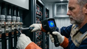
If the selected system includes battery energy storage, treat that as an additional siting review—not a footnote. Confirm equipment listing or certification, ventilation or thermal management, separation, fire-service access, emergency shutdown, signage, and the local authority’s requirements. In the United States, project teams commonly refer to NFPA 855 and relevant listings; UL’s energy-storage installation FAQ explains the relationship between installation codes and product safety standards.
Solar Container Pre-Delivery Site Checklist
- Equipment: exact model, approved arrangement drawing, transport and operating mass, center of gravity, lifting points, support reactions, deployed geometry, operating limits, and stowage requirements.
- Survey: coordinates, boundary and obstacle plan, levels, slope, north direction, photos, drone images where permitted, overhead and underground services, and proposed container orientation.
- Ground: soil description, geotechnical information where required, bearing and settlement assessment, frost and seismic conditions, flood level, and foundation design responsibility.
- Water: rainfall basis, pad grading, runoff route, erosion control, outfall approval, and inspection access for drains.
- Solar: resource dataset, horizon and shading survey, seasonal vegetation, expected soiling, and array orientation assumptions.
- Logistics: route survey, permits, gate and turning checks, delivery vehicle data, lifting method, crane setup and outrigger support, exclusion zone, weather limits, and recovery plan.
- Electrical: load profile, connection voltage and frequency, point of connection, cable route and length, earthing concept, protection study inputs, communications, metering, and grid or generator interface.
- Operations: maintenance clearances, safe access, lighting, security, vegetation control, spare-part access, emergency response, and named site contacts.
- Approvals: planning, building, environmental, electrical, fire, transport, lifting, and utility requirements applicable to the jurisdiction.
Warning Signs That the Proposed Site Needs Redesign
- The only dimension available is the closed container length.
- The support concept assumes the container is “its own foundation.”
- The crane must stand on a drain, trench, soft verge, or unverified fill.
- Deployment would cross a road, fence line, cable route, or emergency path.
- Water already ponds or flows through the proposed support footprint.
- Maintenance requires entering the array’s moving or swept area.
- Exact equipment loads, lifting points, or deployed geometry are still unknown.
- A battery system is proposed without a documented fire and emergency-access review.
Any one of these conditions can change the layout, civil scope, delivery method, or equipment choice. Resolving it before manufacturing and mobilization is usually less disruptive than solving it with the unit already in transit.
Prepare the Inputs for a HighJoule Site Review
Before selecting a fold-out solar container such as the HJ-FESS series, or evaluating a storage-integrated configuration such as the HJ-FBESS series, assemble the checklist information above. The appropriate configuration and site scope depend on the load, solar resource, operating strategy, delivery constraints, and local requirements—not on container size alone.
Submit your site coordinates, load profile, access photos, proposed installation area, and target operating date for a preliminary technical review. HighJoule can use those inputs to identify missing data and coordinate equipment information; the project’s appointed engineers, contractors, and authorities remain responsible for site-specific design and approval.
Last Updated on 07/30/2026