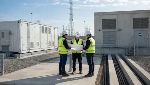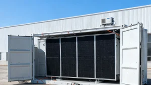
A containerized battery energy storage system (BESS) cannot be treated as grid-ready merely because its power conversion system can operate at the site voltage and frequency. Before a utility application, the project team needs a controlled set of site data, operating assumptions, drawings, protection inputs, and named owners. The utility, interconnecting entity, and local authorities determine the applicable process; the equipment supplier does not approve the interconnection.
This article is for EPC teams, owners, and developers preparing a grid-connected containerized BESS project. Its purpose is to prevent a late discovery that the submitted system configuration, point of interconnection, protection design, communications architecture, or operating-mode assumption does not match the project that the utility is studying.

Start with the point of interconnection, not the container nameplate
The point of interconnection is an electrical boundary used in the applicable utility process. It is the anchor for the application: voltage level, ownership boundary, metering arrangement, transformer connection, protection scheme, export limitation, communications, and operating requirements may all depend on it. Use the utility’s defined terminology for the point of interconnection (POI), point of common coupling (PCC), metering point, service point, and ownership boundary rather than assuming that those terms identify the same physical location. A 20-foot or 40-foot container does not define these requirements.
For a utility-process baseline, the U.S. Department of Energy’s Distributed Energy Interconnection Checklist provides a useful sequence of utility-facing tasks and questions. The DOE BESS Procurement Checklist can then support earlier equipment and project-development inputs. Both are useful planning references, not a replacement for the applicable utility process or local engineering review.
The application-readiness matrix
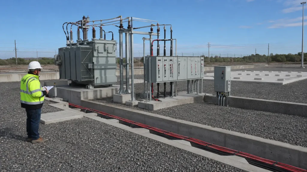
Use the following matrix before the first utility submission. It is designed to show which inputs are ready, who owns them, and what can block an application or later energization. A completed row means that the project team has controlled the input; it does not mean that the utility has accepted it.
| Application input | What must be defined | Responsible project party | External decision or confirmation party | Typical supporting evidence | Hold point if unresolved |
|---|---|---|---|---|---|
| Point of interconnection and project boundary | Location, voltage, ownership boundary, metering, transformer arrangement, and whether the system imports, exports, or both. | Owner / project developer with EPC electrical lead | Utility or interconnecting entity | Site plan, single-line diagram, utility service information, and controlled project basis. | Do not finalize equipment or protection assumptions against an undefined connection boundary. |
| Operating modes and dispatch assumptions | Grid-parallel operation, charging source, POI net-import and net-export limit, islanding intent, black-start requirement, reactive-power or power-factor expectations, and curtailment logic. | Owner / operator with EPC controls lead | Utility where the operating mode or export limit is subject to its process | Operating narrative, load study inputs, control philosophy, and utility requirements where provided. | Do not represent a mode as available until the site design, utility path, and equipment configuration support it. |
| Equipment configuration | PCS model and rating, maximum continuous charge and discharge power, transformer rating, impedance, vector group and grounding arrangement, battery configuration, auxiliary loads, firmware baseline, and communications equipment. | Supplier engineering team with EPC review | Utility or interconnecting entity where it reviews the application input | Controlled technical schedule, single-line diagram, general arrangement, datasheets, and deviation log. | Do not submit family-level documents as proof for an unconfirmed project configuration. |
| Protection, controls, and communications | Protection functions, settings responsibility, PCS fault-current contribution, voltage and frequency ride-through mode, anti-islanding approach, reactive-power or power-factor capability, harmonic or power-quality data, CT and VT interfaces, remote control, telemetry, SCADA ownership, and firmware/software baseline. | EPC electrical and controls leads | Utility where its review, study, or authorization is required | Protection philosophy, interface schedule, cause-and-effect matrix, communications architecture, point list, models where requested, and utility study requirements. | Do not use a PCS capability statement as a substitute for a coordinated protection and controls design. |
| Tests, commissioning, and acceptance | Factory-scope proof, site test sequence, witness points, energization prerequisites, communications verification, and open-item closure path. | EPC commissioning lead with owner and supplier | Utility for permission to energize where applicable; owner for contractual acceptance | FAT protocol, SAT protocol, commissioning plan, punch-list register, and document index. | FAT, shipment release, SAT, utility permission to energize, and operational acceptance remain separate decisions. |
Separate standards from the utility’s project decision
For U.S. projects, IEEE 1547-2018 and applicable amendments may form part of the technical interconnection path where adopted by the relevant authority or utility. IEEE 1547.9-2022 provides guidance on using IEEE 1547 for the interconnection of energy-storage distributed energy resources with electric power systems. The utility’s adopted rules and project-specific requirements still govern the actual submission and approval path. Neither reference is a universal global requirement or a replacement for a utility study, approved settings, communications acceptance, or permission to energize.
The same distinction applies in other jurisdictions. A local grid code, national standard, utility technical rule, project specification, or owner requirement may each apply to a different part of the project. The practical EPC task is to turn each applicable requirement into a controlled submission input, an engineering deliverable, a test point, or a named open item.
BESS utility-application input schedule
Where the utility process requests them, keep the following inputs in a controlled schedule rather than dispersing them across data sheets, drawings, and email threads. The exact submission set and level of detail are determined by the applicable utility process, study scope, and project phase.
| Input group | Examples to control where requested | Typical source and revision owner |
|---|---|---|
| Power and operating envelope | Maximum continuous charging power; maximum continuous discharge or export power; POI net-import and net-export limit; reactive-power or power-factor capability; operating modes and curtailment logic. | Owner / operator operating basis, with EPC controls and supplier configuration input. |
| Electrical interface | Transformer rating, impedance, vector group, and grounding method; PCS fault-current contribution; CT and VT interfaces; metering arrangement; single-line diagram. | EPC electrical lead, using controlled supplier information. |
| Performance and protection | Voltage and frequency ride-through mode; anti-islanding strategy; protection functions and settings responsibility; harmonic or power-quality data; relevant conformance-test information where requested. | EPC protection lead, supplier engineering, and utility process inputs where applicable. |
| Controls, models, and communications | Static or dynamic models; point list; communications protocol; remote-control permissions; telemetry; SCADA ownership; software and firmware version baseline. | EPC controls lead with supplier and owner / operator inputs. |
Use a document sequence rather than a certificate pack
Interconnection submissions often fail because the documents describe different versions of the project. A supplier data sheet may show one PCS rating, a civil drawing another transformer arrangement, and a controls narrative an operating mode that has not been accepted by the owner or utility. The remedy is a document sequence with controlled revisions.
- Lock the project operating basis and point of interconnection.
- Issue the controlled single-line diagram and equipment schedule.
- Map utility and project requirements to the relevant design document, evidence, owner, and due date.
- Submit a controlled configuration that the project team can support with stated assumptions, and clearly identify provisional inputs that remain subject to the utility process or approved change control.
- Record utility questions, design changes, and required studies in one decision log.
- Reassess evidence, protection, controls, and test implications whenever the configuration changes.
For the supplier-side evidence comparison that should support this sequence, use our containerized BESS technical specification checklist. For the broader project ownership and award controls around delivery and handover, use our EPC interface review. Neither article substitutes for the utility’s own interconnection requirements.
What the supplier can provide—and what remains outside the supplier’s approval scope
A supplier can provide configuration-specific technical information, controlled equipment documentation, agreed factory evidence, interface data, and input to the EPC’s engineering process. The supplier cannot unilaterally determine the utility study outcome, final relay settings, protection coordination, interconnection agreement, site construction quality, or authority approval.
Make that boundary visible in the responsibility matrix. The owner or project developer normally owns the project’s commercial and utility relationship. The EPC owns the engineering and site-integration work assigned by contract. The supplier owns the agreed equipment and factory-scope deliverables. The utility retains its own evaluation and authorization decisions.
Do not confuse readiness for submission with readiness to energize
A project can be ready for an application while still needing studies, design revisions, site construction, witness testing, or documentation closure. It can also complete factory acceptance testing while remaining unable to energize because a protection setting, communications link, utility authorization, or site prerequisite is not complete.
Before energization, keep a separate gate that names the prerequisites, evidence, accountable project party, and external authorization that remains pending. This protects the project team from calling a container “commissioned” when only a narrower factory or installation scope has been completed.

When to pause the application
Pause—or submit only as a clearly identified preliminary package where the utility process permits—when the point of interconnection remains provisional; the offered PCS or transformer configuration is not controlled; the project has no agreed operating narrative; protection and communications ownership is undefined; or a required utility input has been replaced with a generic standard reference. An incomplete application can create more rework than a short, controlled clarification phase.
Headquartered in Shanghai, HighJoule manufactures containerized solar and energy storage systems through its production facilities in Jiangsu Province. We can provide configuration information, factory evidence within the agreed scope, and technical input for the project team. The owner, EPC, utility, local engineers, and other responsible parties retain decisions within their own scopes.